
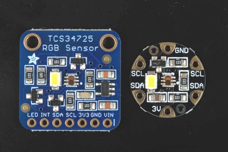
给机器人加视觉感知,第一步往往不是摄像头,而是颜色传感器。判断传送带上的物料是红是绿、让小车跟着色线走、给分拣机构一个可靠的判据——这类活儿交给一颗 TCS34725 就够了。它是 Adafruit 官方教程里点名"市场上最好的颜色传感器",做法也简单:四线 I2C 接上 Arduino 就能出数据。这篇把接线、装库、测试代码和白平衡校准一次讲透。
为什么是 TCS34725:RGBC 四通道加 IR 滤光片
先说器件本身。TCS34725 是 RGBC 四通道方案:Red、Green、Blue 之外还有一路 Clear 通道,不滤颜色、直接收全谱光强。芯片在感光二极管上集成了一片 IR 阻挡滤光片,把红外分量挡掉——这一点很关键,因为白炽灯和阳光里 IR 成分很重,没有滤光片的传感器会拿红外污染 RGB 读数,测出来的"颜色"和人眼看到的对不上。
官方教程给的规格里有个很唬人的数字:3,800,000:1 的动态范围,配合可调积分时间和增益,隔着深色玻璃也能用。积分时间从 2.4ms 到 700ms 分六档,增益分 1X、4X、16X、60X 四档,弱光下拉长积分加高增益,强光下反过来,这正是它比老式 TCS3200 好用的地方。
Adafruit 的扩展板上还做了三件事:板载 3.3V 稳压器,模块可以直接吃 3 到 5V 供电;I2C 引脚做了电平转换,3.3V 和 5V 逻辑都能挂;再配一颗 4150°K 中性白光 LED,带 MOSFET 驱动,用任意逻辑电平就能开关。这颗 LED 是做反射测量的补光用的,后面会讲到它有个不大不小的坑。扩展板有面包板直插版和 Flora 可穿戴版两个版本,原理完全一样。
接线:四根线搞定 I2C
接线只需要四根。官方教程的接法:5V 接 VIN,GND 接 GND,SDA 接 SDA,SCL 接 SCL。I2C 总线本身是 3.3V 电平兼容的,板上稳压器和电平转换已经处理好了,Uno 这类 5V 板直接接没问题。
引脚位置按板子来。教程里写得很明确:Duemilanove 和 R3 之前的 UNO,SDA 在模拟口 A4、SCL 在 A5;R2 之前的 Mega 在数字口 20 和 21;Leonardo 是数字口 2 和 3。R3 及之后的 UNO 板缘已经单独引出了 SDA/SCL,直接对号入座即可。ESP32、树莓派 Pico 这类板子照样能用,认准自家 SDA/SCL 引脚就行。
第三块是 LED 引脚。扩展板上这根引脚拉低即可关灯,默认高电平点亮。想用代码控制,官方库参考的写法是把 LED 引脚接到扩展板的 INT 引脚,然后调 setInterrupt():传 false 点亮 LED 做反射测量,传 true 关灯做入射测量。
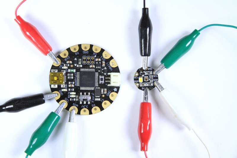
面包板上的四线接法,VIN/GND/SDA/SCL 依次对应
装库与第一段测试代码
软件侧先装官方库。打开 Arduino IDE 的 Manage Libraries 菜单,搜 Adafruit TCS34725 装上即可,会连带装上依赖的统一传感器库。装完直接跑库自带的测试例程,这是官方推荐的第一步。
下面这段是官方库 examples 里的 tcs34725 测试例程,逐字符搬过来不改。唯一替换是第一个 include:站点会剥掉尖括号头文件,把 #include 改成了等价的 #include "Wire.h",编译上两种写法完全一致:
#include "Wire.h"
#include "Adafruit_TCS34725.h"

/* Example code for the Adafruit TCS34725 breakout library */

/* Connect SCL    to analog 5
   Connect SDA    to analog 4
   Connect VDD    to 3.3V DC
   Connect GROUND to common ground */

/* Initialise with default values (int time = 2.4ms, gain = 1x) */
// Adafruit_TCS34725 tcs = Adafruit_TCS34725();

/* Initialise with specific int time and gain values */
Adafruit_TCS34725 tcs = Adafruit_TCS34725(TCS34725_INTEGRATIONTIME_614MS, TCS34725_GAIN_1X);

void setup(void) {
  Serial.begin(9600);

  if (tcs.begin()) {
    Serial.println("Found sensor");
  } else {
    Serial.println("No TCS34725 found ... check your connections");
    while (1);
  }

  // Now we're ready to get readings!
}

void loop(void) {
  uint16_t r, g, b, c, colorTemp, lux;

  tcs.getRawData(&r, &g, &b, &c);
  // colorTemp = tcs.calculateColorTemperature(r, g, b);
  colorTemp = tcs.calculateColorTemperature_dn40(r, g, b, c);
  lux = tcs.calculateLux(r, g, b);

  Serial.print("Color Temp: "); Serial.print(colorTemp, DEC); Serial.print(" K - ");
  Serial.print("Lux: "); Serial.print(lux, DEC); Serial.print(" - ");
  Serial.print("R: "); Serial.print(r, DEC); Serial.print(" ");
  Serial.print("G: "); Serial.print(g, DEC); Serial.print(" ");
  Serial.print("B: "); Serial.print(b, DEC); Serial.print(" ");
  Serial.print("C: "); Serial.print(c, DEC); Serial.print(" ");
  Serial.println(" ");
}
上传后开串口监视器(9600 波特率),先看到 Found sensor 就是 I2C 通了。程序每轮打印五个值:以 K 为单位的色温、lux 照度、R/G/B 三个滤光后的值和 C 这个未滤光值。官方教程建议这时候拿传感器对着不同光源、遮住再放开,观察数值怎么变,先建立手感。
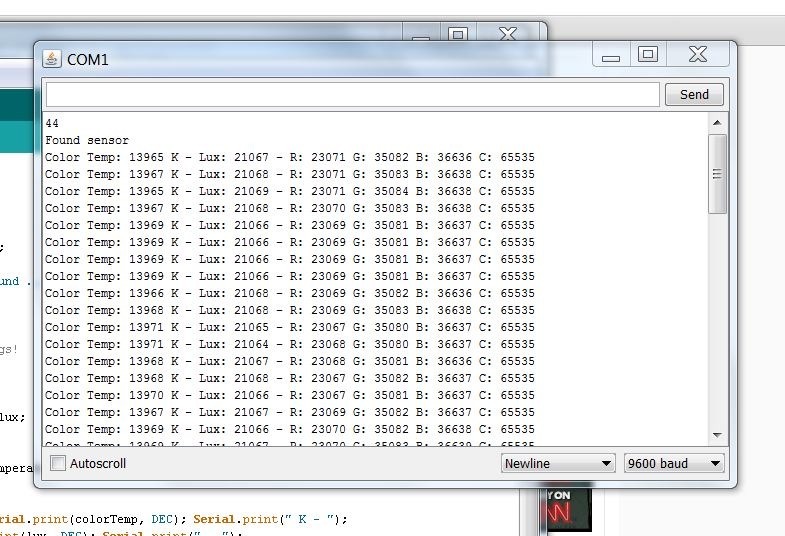
测试例程的串口输出形态,色温、lux、RGBC 一行全给
注意到例程里初始化用的是 614ms 积分时间加 1X 增益,而不是默认的 2.4ms。这是官方例程有意为之:长积分时间对弱光更灵敏,读数更稳,代价是每轮测量更慢。做静态色卡识别没问题,做高速检测就要往下调。
从裸值到 RGB:白平衡校准怎么做
getRawData() 吐出来的是 16 位裸值,四个通道各一份。裸值不能直接当 RGB 用——不同光源、不同增益下数值量级完全不一样。库提供了 calculateColorTemperature() 和 calculateLux() 两个换算函数,新版例程用的是 calculateColorTemperature_dn40(),这个版本把 Clear 通道也算进去,对混光环境的估计更准。
真正做色卡识别,得走"固定条件加标定"的路线。反射测量下,距离、视场角、环境光都在影响读数,官方教程专门开了一节讲这件事:把距离和补光固定下来,先对着白色参考面测一组最大值,再对着黑色参考面测一组最小值,把裸值归一化到 0-255,色卡之间才好划界。
库里自带的 ColorView 例程就是一个现成的白平衡模板。它用板载白光 LED 补光、50ms 积分加 4X 增益读数,再通过一张 2.5 次幂的 gamma 表把 RGB 值转回人眼感知的颜色,驱动一颗 RGB LED 复现看到色。官方给出的接线是:RGB LED 共阳长脚接 5V,红脚串 1K 电阻接 Arduino 3 号脚,绿脚串 560Ω 接 5 号,蓝脚串 560Ω 接 6 号(绿通道偏亮,电阻要大一号):
#include "Wire.h"
#include "Adafruit_TCS34725.h"

// Pick analog outputs, for the UNO these three work well
// use ~560  ohm resistor between Red & Blue, ~1K for green (its brighter)
#define redpin 3
#define greenpin 5
#define bluepin 6
// for a common anode LED, connect the common pin to +5V
// for common cathode, connect the common to ground

// set to false if using a common cathode LED
#define commonAnode true

// our RGB -> eye-recognized gamma color
byte gammatable[256];


Adafruit_TCS34725 tcs = Adafruit_TCS34725(TCS34725_INTEGRATIONTIME_50MS, TCS34725_GAIN_4X);

void setup() {
  Serial.begin(9600);
  //Serial.println("Color View Test!");

  if (tcs.begin()) {
    //Serial.println("Found sensor");
  } else {
    Serial.println("No TCS34725 found ... check your connections");
    while (1); // halt!
  }

  // use these three pins to drive an LED
#if defined(ARDUINO_ARCH_ESP32)
  ledcAttach(redpin, 12000, 8);
  ledcAttach(greenpin, 12000, 8);
  ledcAttach(bluepin, 12000, 8);
#else
  pinMode(redpin, OUTPUT);
  pinMode(greenpin, OUTPUT);
  pinMode(bluepin, OUTPUT);
#endif

  // thanks PhilB for this gamma table!
  // it helps convert RGB colors to what humans see
  for (int i=0; i<256; i++) {
    float x = i;
    x /= 255;
    x = pow(x, 2.5);
    x *= 255;

    if (commonAnode) {
      gammatable[i] = 255 - x;
    } else {
      gammatable[i] = x;
    }
    //Serial.println(gammatable[i]);
  }
}

// The commented out code in loop is example of getRawData with clear value.
// Processing example colorview.pde can work with this kind of data too, but It requires manual conversion to
// [0-255] RGB value. You can still uncomments parts of colorview.pde and play with clear value.
void loop() {
  float red, green, blue;

  tcs.setInterrupt(false);  // turn on LED

  delay(60);  // takes 50ms to read

  tcs.getRGB(&red, &green, &blue);

  tcs.setInterrupt(true);  // turn off LED

  Serial.print("R:\t"); Serial.print(int(red));
  Serial.print("\tG:\t"); Serial.print(int(green));
  Serial.print("\tB:\t"); Serial.print(int(blue));

//  Serial.print("\t");
//  Serial.print((int)red, HEX); Serial.print((int)green, HEX); Serial.print((int)blue, HEX);
  Serial.print("\n");

//  uint16_t red, green, blue, clear;
//
//  tcs.setInterrupt(false);  // turn on LED
//
//  delay(60);  // takes 50ms to read
//
//  tcs.getRawData(&red, &green, &blue, &clear);
//
//  tcs.setInterrupt(true);  // turn off LED
//
//  Serial.print("C:\t"); Serial.print(int(clear));
//  Serial.print("R:\t"); Serial.print(int(red));
//  Serial.print("\tG:\t"); Serial.print(int(green));
//  Serial.print("\tB:\t"); Serial.print(int(blue));
//  Serial.println();


#if defined(ARDUINO_ARCH_ESP32)
  ledcWrite(1, gammatable[(int)red]);
  ledcWrite(2, gammatable[(int)green]);
  ledcWrite(3, gammatable[(int)blue]);
#else
  analogWrite(redpin, gammatable[(int)red]);
  analogWrite(greenpin, gammatable[(int)green]);
  analogWrite(bluepin, gammatable[(int)blue]);
#endif
}
例程里 setInterrupt(false) 点亮补光、delay(60) 等满 50ms 的积分窗口、getRGB() 取 0-255 的换算值,这一套节奏照抄就能跑。换你自己的色卡识别逻辑时,把这个节奏保留,读数稳定性就有底。想更进一步,Adafruit 论坛上有玩家 systembolaget 用 TCS34725 加舵机做了个颜色分拣机,教程和仓库都公开,把他的标定思路搬过来用很划算。

库管理器里搜 Adafruit TCS34725,一键安装
常见坑:LED 引脚、积分时间和多传感器
第一个坑就是 LED 引脚。很多人以为 LED 引脚直接给高电平调亮度,实际上它只是开关:拉低关灯、放开点亮,没有中间态。想用代码控制,务必按官方库参考说的把 LED 接到 INT 引脚再用 setInterrupt() 切换,否则反射测量的补光始终不受控。
第二个坑是积分时间。设了 50ms 积分就得 delay 至少 50ms 再取数,ColorView 例程给的是 delay(60) 留了余量。积分时间设长而循环读得快,拿到的就是旧数据甚至半截数据。反过来,如果你发现读数饱和(RGB 全顶到很高),先把积分时间调短或增益调低,再怀疑别处。
第三个是多传感器场景。TCS34725 的 I2C 地址固定,一颗总线上挂两颗会冲突,官方库也没提供改地址的口子。要同时读多路颜色,标准解法是在中间加一颗 I2C 多路复用器,把每颗传感器挂到不同通道上,代码里切通道再读,方法本身和传感器无关。
最后给个选型视角的收尾:如果你的场景只问"亮不亮",光敏电阻够用;要分辨颜色并且抗红外干扰,TCS34725 是这一档里最稳的方案之一;做高速产线检测则要掂量 2.4ms 积分时间对应的读数上限和增益噪声的取舍。器件没有万能,把规格表的边界摸清楚,选型就不会翻车。



写得很细,尤其是把库参考里 setInterrupt 控制 LED 那个点讲清楚了。我之前把 LED 引脚当 PWM 用,怎么都不亮,后来才发现它就是个开关:拉低关灯、放开点亮,想用代码控制必须接 INT 引脚。早看到这篇能少绕半小时弯路。
白平衡那段实用,先定距离和补光,再拿黑白参考面标定,比直接拿裸值比靠谱多了。
GAIN_4X 那档确实够用,室内反射测量我一般 50ms 积分起步,读数抖动明显小。
终于有人讲积分时间和 delay 的关系了,50ms 就得等 60ms,这个坑我踩过。