
给机械臂或者六足机器人装舵机,最头疼的不是舵机贵,是引脚不够。Arduino Uno 一共就那么几个 PWM 口,Servo 库每挂一个舵机还要吃掉一个数字引脚和一部分定时器资源,装到第 4 个臂关节,板子已经没口可分了。PCA9685 就是干这个的:一块 16 路 12 位 PWM 驱动板,走 I2C 总线,只占 SDA、SCL 两根线,16 个舵机同时动,主控几乎不额外开销。更夸张的是它最多能级联 62 块板,理论上 992 路输出,还是那两根线。这套接法和库都来自 Adafruit 官方教程,下面把接线、地址、代码和供电的坑一次说清。
为什么是 PCA9685,不是多堆几块 Arduino
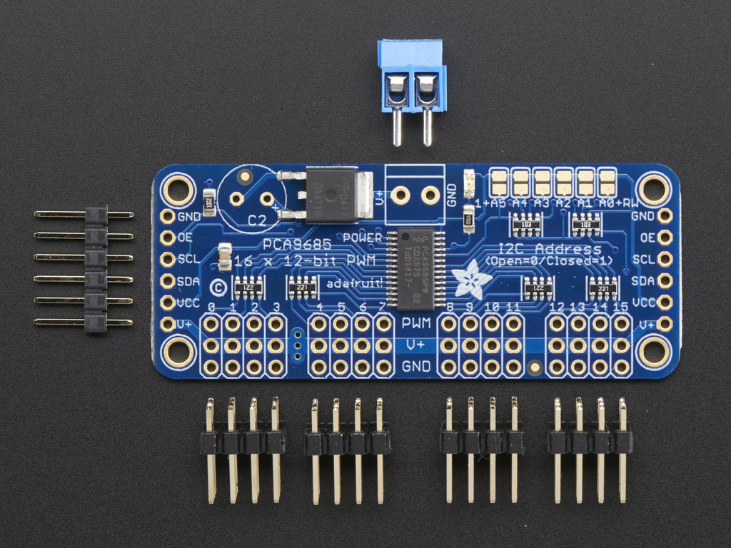
PCA9685 板载一颗独立的 PWM 控制器(芯片丝印就是 PCA9685),主控只负责通过 I2C 下发寄存器值,16 路输出由芯片自己维持,Arduino 的 loop() 里爱干什么干什么。每路是 12 位分辨率,4096 级;16 路完全独立,但共享同一个 PWM 频率——舵机用 50Hz 一档就对了,想一半路驱动舵机、一半路调 LED 闪 1kHz 是做不到的。
每个输出端口有 3 个针:V+、GND 和 PWM 信号。PWM 线上串了 220 欧电阻,单脚最大电流 25mA,直接插舵机信号线正好。板子默认 I2C 地址 0x40,两侧的控制排针完全等价,随便用哪边,级联时也从这边方便。
接线:主控侧 4 根线搞定
对经典 Uno,接法是:5V 接 VCC(这路只给板子芯片供电,不是舵机电源)、GND 接 GND、A4 接 SDA、A5 接 SCL。R3 及以后的 Uno、Mega、Leonardo 板上 USB 座旁边那组有专门的 SDA/SCL 排针,直接对位接更省事;老 Mega 用数字 20 当 SDA、21 当 SCL。
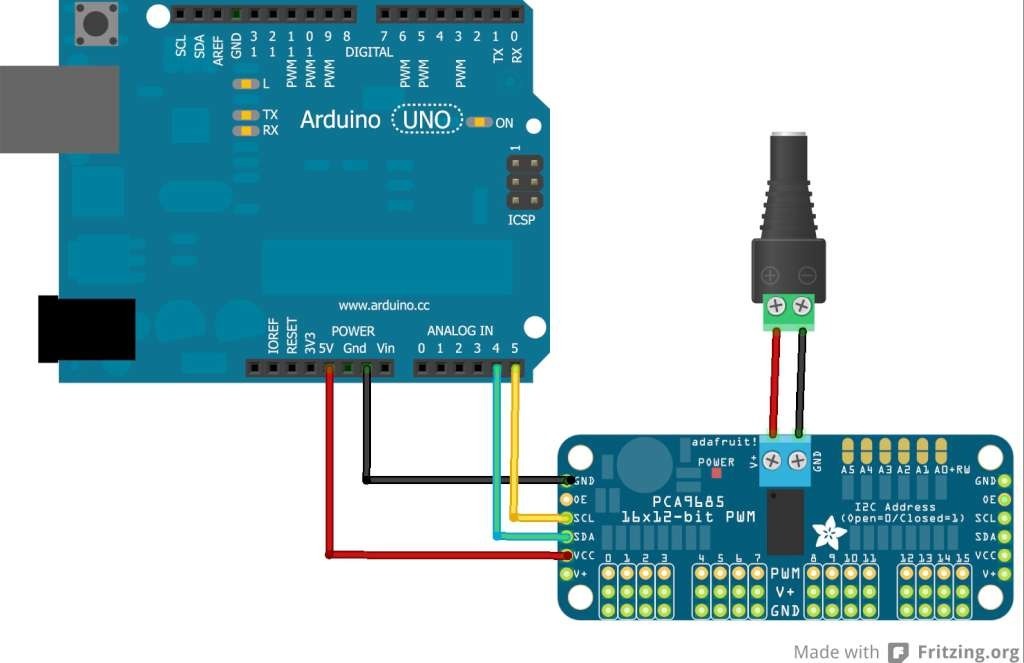
有两个容易混的电源针。VCC 是逻辑电源,接 3 到 5V,要和主控逻辑电平一致,因为 SCL/SDA 的 10K 上拉靠它;V+ 是给舵机分布供电的,不接芯片本身,不用舵机可以悬空,也可以从板顶那个蓝色接线端子灌进去。V+ 建议 5-6V,最高能到 6V,就算 VCC 是 3.3V 也没关系,芯片 5V 安全。官方教程特别强调走蓝色端子供电,因为这条路有极性保护。
还有一颗 OE 引脚,拉高会关掉全部输出,默认拉低即全开,不接也行,想一键急停可以接个开关。
地址设置与级联到 62 块板
板上边缘有 A0-A5 六个地址跳线焊盘,默认全开就是 0x40。要改地址,用焊锡把对应焊盘桥上,桥上的位按二进制 1 加进基址:Board 1 桥 A0 得 0x41,Board 2 桥 A1 得 0x42,Board 3 桥 A0 和 A1 得 0x43,依次类推。板子两头都有排针,一块块用 6 针并排线串起来就行,最多 62 块共 992 路。
代码里每块板声明一个对象,各自 begin、各自控制:
#include "Wire.h"
#include "Adafruit_PWMServoDriver.h"

Adafruit_PWMServoDriver pwm1 = Adafruit_PWMServoDriver(0x40);
Adafruit_PWMServoDriver pwm2 = Adafruit_PWMServoDriver(0x41);

void setup() {
  Serial.begin(9600);
  Serial.println("16 channel PWM test!");

  pwm1.begin();
  pwm1.setPWMFreq(1600);  // This is the maximum PWM frequency

  pwm2.begin();
  pwm2.setPWMFreq(1600);  // This is the maximum PWM frequency
}
顺带一句:尖括号形式的头文件在这套平台上会被剥掉,所以上面写成引号形式,两种写法对库搜索路径是编译等价的,不影响使用。
装库、跑示例、校准行程
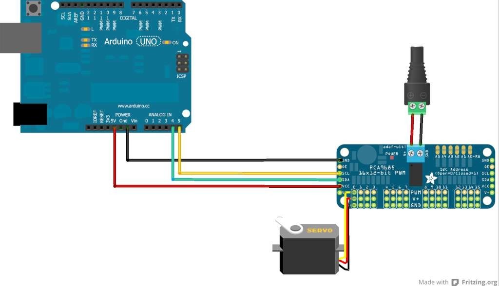
库管理器里搜 adafruit pwm,装 Adafruit_PWMServoDriver 库(代码在 Adafruit 官方 GitHub 仓库),然后打开 File、Examples、Adafruit_PWMServoDriver、Servo 这个示例,接上驱动板和一个插在 0 号口的舵机,绿灯亮着就说明板子通电正常,舵机应该在约 180 度范围来回扫。示例代码全文如下,逐字符照搬:
/***************************************************
  This is an example for our Adafruit 16-channel PWM & Servo driver
  Servo test - this will drive 8 servos, one after the other on the
  first 8 pins of the PCA9685

  Pick one up today in the adafruit shop!
  ------> http://www.adafruit.com/products/815

  These drivers use I2C to communicate, 2 pins are required to
  interface.

  Adafruit invests time and resources providing this open source code,
  please support Adafruit and open-source hardware by purchasing
  products from Adafruit!

  Written by Limor Fried/Ladyada for Adafruit Industries.
  BSD license, all text above must be included in any redistribution
 ****************************************************/

#include "Wire.h"
#include "Adafruit_PWMServoDriver.h"

// called this way, it uses the default address 0x40
Adafruit_PWMServoDriver pwm = Adafruit_PWMServoDriver();
// you can also call it with a different address you want
//Adafruit_PWMServoDriver pwm = Adafruit_PWMServoDriver(0x41);
// you can also call it with a different address and I2C interface
//Adafruit_PWMServoDriver pwm = Adafruit_PWMServoDriver(0x40, Wire);

// Depending on your servo make, the pulse width min and max may vary, you
// want these to be as small/large as possible without hitting the hard stop
// for max range. You'll have to tweak them as necessary to match the servos you
// have!
#define SERVOMIN  150 // This is the 'minimum' pulse length count (out of 4096)
#define SERVOMAX  600 // This is the 'maximum' pulse length count (out of 4096)
#define USMIN  600 // This is the rounded 'minimum' microsecond length based on the minimum pulse of 150
#define USMAX  2400 // This is the rounded 'maximum' microsecond length based on the maximum pulse of 600
#define SERVO_FREQ 50 // Analog servos run at ~50 Hz updates

// our servo # counter
uint8_t servonum = 0;

void setup() {
  Serial.begin(9600);
  Serial.println("8 channel Servo test!");

  pwm.begin();
  /*
   * In theory the internal oscillator (clock) is 25MHz but it really isn't
   * that precise. You can 'calibrate' this by tweaking this number until
   * you get the PWM update frequency you're expecting!
   * The int.osc. for the PCA9685 chip is a range between about 23-27MHz and
   * is used for calculating things like writeMicroseconds()
   * Analog servos run at ~50 Hz updates, It is importaint to use an
   * oscilloscope in setting the int.osc frequency for the I2C PCA9685 chip.
   * 1) Attach the oscilloscope to one of the PWM signal pins and ground on
   *    the I2C PCA9685 chip you are setting the value for.
   * 2) Adjust setOscillatorFrequency() until the PWM update frequency is the
   *    expected value (50Hz for most ESCs)
   * Setting the value here is specific to each individual I2C PCA9685 chip and
   * affects the calculations for the PWM update frequency.
   * Failure to correctly set the int.osc value will cause unexpected PWM results
   */
  pwm.setOscillatorFrequency(27000000);
  pwm.setPWMFreq(SERVO_FREQ);  // Analog servos run at ~50 Hz updates

  delay(10);
}

// You can use this function if you'd like to set the pulse length in seconds
// e.g. setServoPulse(0, 0.001) is a ~1 millisecond pulse width. It's not precise!
void setServoPulse(uint8_t n, double pulse) {
  double pulselength;

  pulselength = 1000000;   // 1,000,000 us per second
  pulselength /= SERVO_FREQ;   // Analog servos run at ~60 Hz updates
  Serial.print(pulselength); Serial.println(" us per period");
  pulselength /= 4096;  // 12 bits of resolution
  Serial.print(pulselength); Serial.println(" us per bit");
  pulse *= 1000000;  // convert input seconds to us
  pulse /= pulselength;
  Serial.println(pulse);
  pwm.setPWM(n, 0, pulse);
}

void loop() {
  // Drive each servo one at a time using setPWM()
  Serial.println(servonum);
  for (uint16_t pulselen = SERVOMIN; pulselen < SERVOMAX; pulselen++) {
    pwm.setPWM(servonum, 0, pulselen);
  }

  delay(500);
  for (uint16_t pulselen = SERVOMAX; pulselen > SERVOMIN; pulselen--) {
    pwm.setPWM(servonum, 0, pulselen);
  }

  delay(500);

  // Drive each servo one at a time using writeMicroseconds(), it's not precise due to calculation rounding!
  // The writeMicroseconds() function is used to mimic the Arduino Servo library writeMicroseconds() behavior.
  for (uint16_t microsec = USMIN; microsec < USMAX; microsec++) {
    pwm.writeMicroseconds(servonum, microsec);
  }

  delay(500);
  for (uint16_t microsec = USMAX; microsec > USMIN; microsec--) {
    pwm.writeMicroseconds(servonum, microsec);
  }

  delay(500);

  servonum++;
  if (servonum > 7) servonum = 0; // Testing the first 8 servo channels
}
舵机行程校准必须做。不同品牌甚至同批个体,脉宽上下限都有差异,示例里 SERVOMIN、SERVOMAX 是计数 150 到 600(对应约 600 到 2400 微秒)。调法是逐步逼近:先改 SERVOMIN 直到扫到你要的 0 度位置就停,再改 SERVOMAX 定 180 度。官方教程专门标了警告,别顶着机械极限调,打满行程会扫齿,舵机直接报废。角度换算用一行 map(degrees, 0, 180, SERVOMIN, SERVOMAX) 就够。
供电踩坑:别用 Arduino 的 5V 带舵机
这是这套板子最大的坑。多数舵机标称 5-6V,微舵动起来也要几百毫安,大扭矩舵机堵转下单只可以超过 1A。官方教程明确说不要从 Arduino 的 5V 引脚取电给舵机——电流一拉,噪声和电压跌落会让主控乱跳、复位甚至发热。靠谱的选择是 5V 2A 或 5V 10A 开关电源,或者 4 节 5 号电池(碱性 6V、镍氢 4.8V)、航模店的 4.8/6V 镍氢电池组。多舵机同时动时电源会明显下坠,板子 PCB 上预留了电解电容位,官方给的估法是每路舵机约 100uF,5 个舵机从 470uF 起步往上加。
还有个隐蔽的坑是地址冲突:PCA9685 除了 0x40 还有一个 All Call 地址 0x70,和 Adafruit 自家的 LED 矩阵/数码管 Backpack 同用时,如果把 Backpack 也留默认 0x70,总线上会互相干扰,把 Backpack 改到 0x71 以外的地址即可。反过来,想全关 LED 输出要写 setPWM(pin, 0, 4096),写 4095 是关不干净的,这是 FAQ 里给的答案。
总结下来,PCA9685 的价值不在"多",而在把"多路 PWM"从主控手里完全卸载:两根 I2C 线、一个地址、一份库代码,16 路就位;级联焊盘一桥,再翻几倍。给六足、机械臂这种人形级多关节项目做前置驱动,是目前最省心也最便宜的路径之一,十几块钱一块板,值得在工具箱里常备两块。



SERVOMIN/SERVOMAX 那个扫齿警告太真实了,我第一次调就把 9g 舵机扫坏了,调参一定要逐步逼近。
请问这个板子和 esp32 能直接接吗,3.3V 逻辑要不要加电平转换?
这套东西我去年装过一块,当时最大的坑就是供电:图省事直接从 Uno 的 5V 引脚带 4 个 SG90,结果舵机一动板子就重启,串口乱码。后来换了 5V 2A 开关电源从蓝色端子灌进去,问题立刻消失。Adafruit 教程里那句不要用 Arduino 5V 带舵机是血的教训换来的,新手千万别省这个电源钱。
级联那段实用,焊盘桥 A0 变 0x41 这个讲清楚了,之前一直没搞明白地址偏移怎么算。