
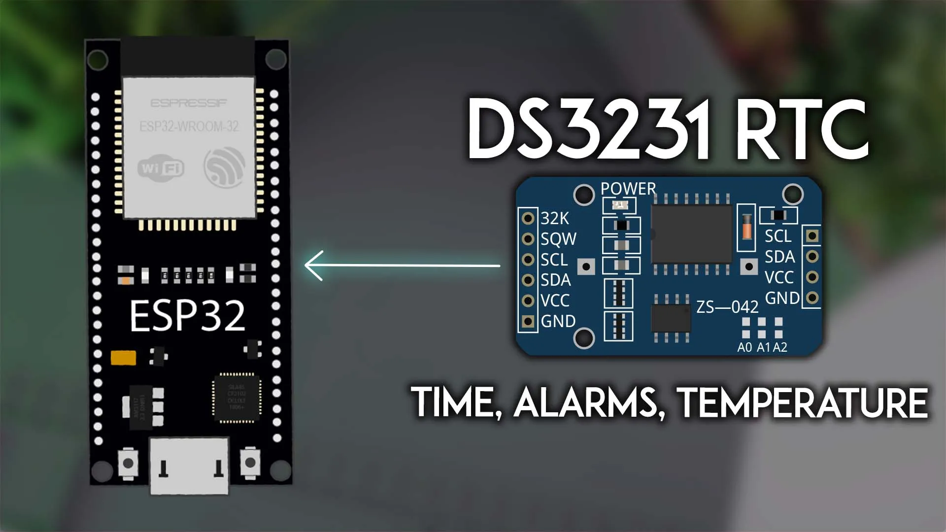
 刚入坑那会儿我以为读时间是件最简单的事:芯片里取一下不就行了?后来才搞明白,ESP32 这类芯片自己并没有掉电保命的时钟,一断电、一重启,时间就从头数。想让定时喂食、数据记录、按时间触发的自动化这些功能真的能用,就得请一块专门的实时时钟模块出场。这篇是我把 Adafruit 官方 RTClib 库的示例文档理顺之后写成的入门笔记,接线、代码和参数都逐项对照过原文,新手可以放心照着做。
断电不丢时间的秘密:RTC 模块是干嘛的
RTC 模块的 full name 是 Real Time Clock,实时时钟。它自己带着一颗小小的时钟芯片,靠一块纽扣电池单独供电,主控断电、重启它都照常走时,时间一点不丢。常见的型号是 DS3231 和 DS1307,两个都能配 ESP32,都走 I2C 通信。
两者里我更推荐 DS3231。它的优势是带温度补偿:内部用了一颗 32kHz 的温补晶体振荡器(TCXO),走时精度不太受气温变化影响,而且芯片还能顺手把测到的温度报给你。另外 DS3231 支持设置两个硬件闹钟,闹钟一响还能反过来唤醒主控,做定时任务特别合适。
价格方面,这种模块在网购平台上一般十块钱上下就能拿下,属于买了基本不会吃灰的器件。只要你的项目里出现"记住现在几点了"或者"到点干某件事"的需求,它就派得上用场。
引脚、电池与 I2C 地址:上电前先认识模块
先看模块本尊。常见的 DS3231 模块(比如 ZS-042 这款蓝色小板)一侧有六个引脚,作用如下表。
| 引脚 | 作用 |
|---|---|
| 32K | 32kHz 时钟信号输出,可当别的设备的时钟基准 |
| SQW | 方波/中断输出脚,闹钟触发时会拉低 |
| SCL | I2C 时钟线 |
| SDA | I2C 数据线 |
| VCC | 供电,3.3V 或 5V 都可以 |
| GND | 地线 |
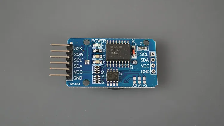 除了走时,模块还能输出 1Hz、4kHz、8kHz、32kHz 四种方波,也自带一颗 24C32 EEPROM 存非易失数据。RTC 芯片本身的 I2C 地址是 0x68,那颗 EEPROM 是 0x57。不确定地址对不对的时候,跑一个 I2C 扫描程序就能确认。
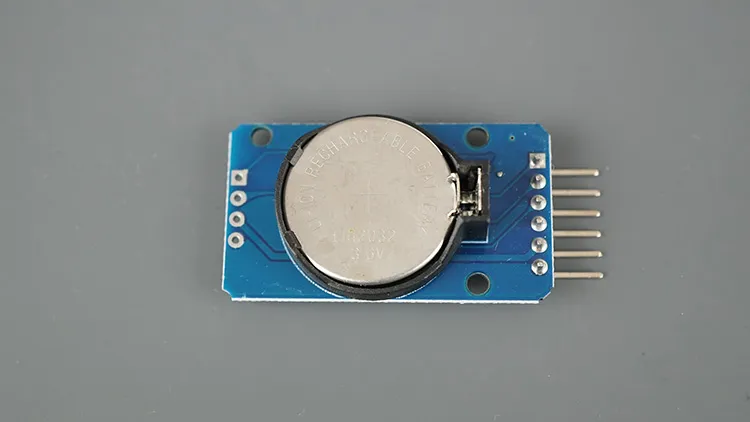 电池这块有个劝退点要说在前面。模块的电池座官方推荐装可充电的 LIR2032,不要装普通不可充电的 CR2032——因为模块自带充电电路,会一直给电池充电。如果你手头只有 CR2032 又非要用,官方教程的做法是:把二极管旁边那颗充电限流电阻(原帖那块板上标号 R4)焊下来,断开充电回路再用。新手我建议直接买 LIR2032,省事也安全。
接线与装库:四根杜邦线加一个库
接线非常简单,五根线里其实主要就四根:I2C 两根、供电两根,外加 SQW 一根留给闹钟用。对照表如下。
| DS3231 模块 | ESP32 |
|---|---|
| SQW | GPIO 4(其他数字脚也行) |
| SCL | GPIO 22 |
| SDA | GPIO 21 |
| VCC | 3V3 |
| GND | GND |
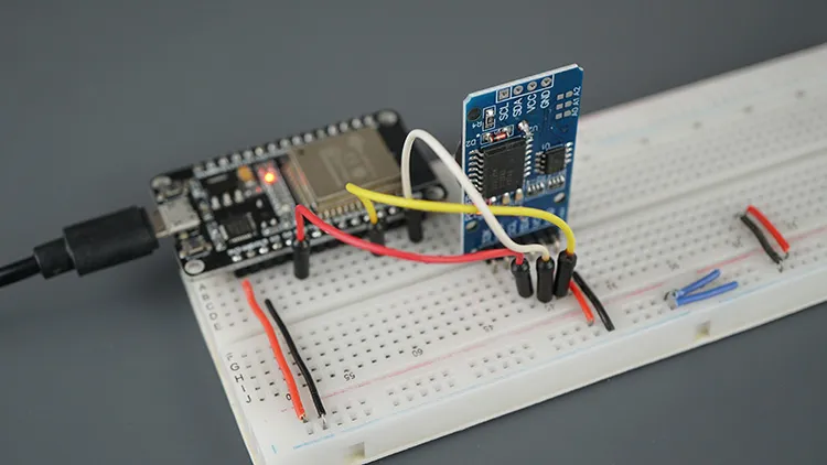 要用 Arduino UNO 这类板子也一样能玩,模块协议就是 I2C,把 SDA、SCL 接到所用板子的对应 I2C 引脚即可,具体脚位以开发板的引脚图为准。接完线建议先肉眼复查一遍正负极,再上电。
软件这边在 Arduino IDE 里操作:打开 Sketch、Include Library、Manage Libraries,搜索 RTCLib,装 Adafruit 出品的那一个。Adafruit 的 RTClib 同时兼容 DS1307、DS3231 和 PCF8523 三种 RTC 芯片,ESP32 也能正常使用。原教程使用的版本是 2.1.4,装新版遇到接口对不上时,可以先回到这个版本试试。
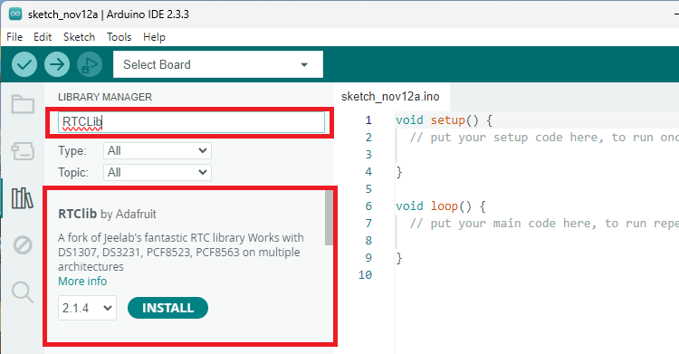 装库这一步经常被新手忽略,然后代码第一行就报错找不到头文件。库装好了,下面就可以上传第一段程序了。
读时间:第一段完整代码
第一段程序做两件事:给 RTC 设一次时间,然后每三秒从模块读回当前时间和芯片温度,打到串口监视器。整段代码如下,可整段复制上传。
/*********
  Rui Santos & Sara Santos - Random Nerd Tutorials
  Complete instructions at https://RandomNerdTutorials.com/esp32-ds3231-real-time-clock-arduino/
*********/

// Based on the RTCLib Library examples: https://github.com/adafruit/RTClib
// Date and time functions using a DS1307 RTC connected via I2C and Wire lib
#include "RTClib.h"

RTC_DS3231 rtc;

char daysOfTheWeek[7][12] = {"Sunday", "Monday", "Tuesday", "Wednesday", "Thursday", "Friday", "Saturday"};

void setup () {
  Serial.begin(115200);

  if (! rtc.begin()) {
    Serial.println("Couldn't find RTC");
    Serial.flush();
    while (1) delay(10);
  }

  if (rtc.lostPower()) {
    Serial.println("RTC lost power, let's set the time!");
    // When time needs to be set on a new device, or after a power loss, the
    // following line sets the RTC to the date & time this sketch was compiled
    rtc.adjust(DateTime(F(__DATE__), F(__TIME__)));
    // This line sets the RTC with an explicit date & time, for example to set
    // January 21, 2014 at 3am you would call:
    //rtc.adjust(DateTime(2014, 1, 21, 3, 0, 0));
  }

  // When time needs to be re-set on a previously configured device, the
  // following line sets the RTC to the date & time this sketch was compiled
  //rtc.adjust(DateTime(F(__DATE__), F(__TIME__)));
  // This line sets the RTC with an explicit date & time, for example to set
  // January 21, 2014 at 3am you would call:
  //rtc.adjust(DateTime(2014, 1, 21, 3, 0, 0));
}

void loop () {
  // Get the current time from the RTC
  DateTime now = rtc.now();

  // Getting each time field in individual variables
  // And adding a leading zero when needed;
  String yearStr = String(now.year(), DEC);
  String monthStr = (now.month() < 10 ? "0" : "") + String(now.month(), DEC);
  String dayStr = (now.day() < 10 ? "0" : "") + String(now.day(), DEC);
  String hourStr = (now.hour() < 10 ? "0" : "") + String(now.hour(), DEC);
  String minuteStr = (now.minute() < 10 ? "0" : "") + String(now.minute(), DEC);
  String secondStr = (now.second() < 10 ? "0" : "") + String(now.second(), DEC);
  String dayOfWeek = daysOfTheWeek[now.dayOfTheWeek()];

  // Complete time string
  String formattedTime = dayOfWeek + ", " + yearStr + "-" + monthStr + "-" + dayStr + " " + hourStr + ":" + minuteStr + ":" + secondStr;

  // Print the complete formatted time
  Serial.println(formattedTime);

  // Getting temperature
  Serial.print(rtc.getTemperature());
  Serial.println("ºC");

  Serial.println();
  delay(3000);
}
说明一句:原代码里的头文件写法是尖括号 include,因为发布平台会把尖括号当成 HTML 标签剥掉,这里换成了等价的引号写法 #include "RTClib.h",两种写法在 Arduino 工具链下搜索库路径的效果是一样的,不影响编译。
代码的思路拆开看。setup() 里先 rtc.begin() 初始化,没找到模块就直接停在提示信息上;然后用 rtc.lostPower() 判断模块是不是新上的或者掉过电,是的话用 rtc.adjust() 把时间拨到"这段代码编译那一刻",__DATE__ 和 __TIME__ 这两个宏会自动带上编译时的日期和时间。也可以手动指定,写法是 rtc.adjust(DateTime(2014, 1, 21, 3, 0, 0)),参数顺序是年、月、日、时、分、秒。
loop() 里 rtc.now() 每三秒取一次时间,返回的 DateTime 对象可以用 now.year()、now.month()、now.day()、now.hour()、now.minute()、now.second() 逐个取字段,now.dayOfTheWeek() 返回 0 到 6,0 是周日。代码里给月、日、时、分、秒都补了前导零,显示出来才是 03:05:06 而不是 3:5:6。温度用 rtc.getTemperature() 拿,返回摄氏度。
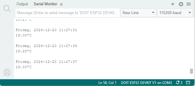
上传后打开串口监视器,波特率选 115200,就能看到时间一行行滚出来,末尾跟着温度。上电那一刻 RTC 被写入了编译时间,之后拔掉 USB 只留电池,模块自己继续走时,再上电时间依然是准的——这就是开头说的"掉电不丢"。
设闹钟:SQW 引脚触发中断
DS3231 能存两个闹钟。闹钟触发时,SQW 引脚会输出低电平,把它接到 ESP32 的 GPIO 上就能触发中断,甚至可以从 deep sleep 里把板子唤醒,做定时唤醒、周期任务都很实用。两个闹钟各有多种触发模式,如下表。
| 闹钟 | 模式 | 触发时机 |
|---|---|---|
| 闹钟 1 | DS3231_A1_PerSecond | 每秒 |
| 闹钟 1 | DS3231_A1_Second | 秒匹配时 |
| 闹钟 1 | DS3231_A1_Minute | 分钟匹配时 |
| 闹钟 1 | DS3231_A1_Hour | 小时匹配时 |
| 闹钟 1 | DS3231_A1_Date | 日期匹配时 |
| 闹钟 1 | DS3231_A1_Day | 星期匹配时 |
| 闹钟 2 | DS3231_A2_PerMinute | 每分钟 |
| 闹钟 2 | DS3231_A2_Minute | 分钟匹配时 |
| 闹钟 2 | DS3231_A2_Hour | 小时匹配时 |
| 闹钟 2 | DS3231_A2_Date | 日期匹配时 |
| 闹钟 2 | DS3231_A2_Day | 星期匹配时 |
官方库示例的逻辑是:先设闹钟 1,触发后清掉标志,再换闹钟 2 上场。有几条使用规则要先记住:同一时刻只能有一个闹钟处于激活状态;闹钟触发后必须清标志位,否则会反复触发把程序搞崩;换闹钟之前要先禁用另一个。完整代码如下。
/*********
  Rui Santos & Sara Santos - Random Nerd Tutorials
  Complete instructions at https://RandomNerdTutorials.com/esp32-ds3231-real-time-clock-arduino/
*********/

// Example based on the RTClib: implementation of an alarm using DS3231 https://github.com/adafruit/RTClib
#include "RTClib.h"
RTC_DS3231 rtc;

char daysOfTheWeek[7][12] = {"Sunday", "Monday", "Tuesday", "Wednesday", "Thursday", "Friday", "Saturday"};

// the pin that is connected to SQW
#define CLOCK_INTERRUPT_PIN 4

// LED for visual indication
const int ledPin = 2;

// set the alarms
// (year, month, day, hour, minutes, seconds)
DateTime alarm1Time = DateTime(2024, 12, 18, 12, 49, 0);
DateTime alarm2Time = DateTime(2024, 12, 18, 11, 10, 0);

void printCurrentTime(){
  // Get the current time from the RTC
  DateTime now = rtc.now();

  // Getting each time field in individual variables
  // And adding a leading zero when needed;
  String yearStr = String(now.year(), DEC);
  String monthStr = (now.month() < 10 ? "0" : "") + String(now.month(), DEC);
  String dayStr = (now.day() < 10 ? "0" : "") + String(now.day(), DEC);
  String hourStr = (now.hour() < 10 ? "0" : "") + String(now.hour(), DEC);
  String minuteStr = (now.minute() < 10 ? "0" : "") + String(now.minute(), DEC);
  String secondStr = (now.second() < 10 ? "0" : "") + String(now.second(), DEC);
  String dayOfWeek = daysOfTheWeek[now.dayOfTheWeek()];

  // Complete time string
  String formattedTime = dayOfWeek + ", " + yearStr + "-" + monthStr + "-" + dayStr + " " + hourStr + ":" + minuteStr + ":" + secondStr;

  // Print the complete formatted time
  Serial.println(formattedTime);
}

void onAlarm() {
  Serial.println("Alarm occurred!");
  // toggle the current LED state
  int state = digitalRead(ledPin);
  digitalWrite(ledPin, !state);
}

void setup() {
  Serial.begin(115200);
  pinMode (ledPin, OUTPUT);
  digitalWrite(ledPin, LOW);

  // initializing the rtc
  if(!rtc.begin()) {
    Serial.println("Couldn't find RTC!");
    Serial.flush();
    while (1) delay(10);
  }

  if(rtc.lostPower()) {
    // this will adjust to the date and time at compilation
    rtc.adjust(DateTime(F(__DATE__), F(__TIME__)));
  }
  // Uncomment if you need to adjust the time
  // rtc.adjust(DateTime(F(__DATE__), F(__TIME__)));

  //we don't need the 32K Pin, so disable it
  rtc.disable32K();

  // Trigger an interrupt when the alarm happens
  pinMode(CLOCK_INTERRUPT_PIN, INPUT_PULLUP);
  attachInterrupt(digitalPinToInterrupt(CLOCK_INTERRUPT_PIN), onAlarm, FALLING);

  // set alarm 1, 2 flag to false (so alarm 1, 2 didn't happen so far)
  // if not done, this easily leads to problems, as both register aren't reset on reboot/recompile
  rtc.clearAlarm(1);
  rtc.clearAlarm(2);

  // stop oscillating signals at SQW Pin, otherwise setAlarm1 will fail
  rtc.writeSqwPinMode(DS3231_OFF);

  // turn off alarm 2 (in case it isn't off already)
  // again, this isn't done at reboot, so a previously set alarm could easily go overlooked
  rtc.disableAlarm(2);

  // Schedule Alarm1 to fire when the minutes match
  if(!rtc.setAlarm1(alarm1Time, DS3231_A1_Minute)) {  // this mode triggers the alarm when the minutes match
    Serial.println("Error, alarm wasn't set!");
  }else {
    Serial.println("Alarm 1 will happen at specified time");
  }
}

void loop() {
  // print current date and time
  printCurrentTime();

  // Get Details about the alarm1
  DateTime alarm1 = rtc.getAlarm1();
  Ds3231Alarm1Mode alarm1mode = rtc.getAlarm1Mode();
  char alarm1Date[12] = "DD hh:mm:ss";
  alarm1.toString(alarm1Date);
  Serial.print("[Alarm1: ");
  Serial.print(alarm1Date);
  Serial.print(", Mode: ");
  switch (alarm1mode) {
    case DS3231_A1_PerSecond: Serial.print("PerSecond"); break;
    case DS3231_A1_Second: Serial.print("Second"); break;
    case DS3231_A1_Minute: Serial.print("Minute"); break;
    case DS3231_A1_Hour: Serial.print("Hour"); break;
    case DS3231_A1_Date: Serial.print("Date"); break;
    case DS3231_A1_Day: Serial.print("Day"); break;
  }
  // the value at SQW-Pin (because of pullup 1 means no alarm)
  Serial.print("] SQW: ");
  Serial.print(digitalRead(CLOCK_INTERRUPT_PIN));
  // whether a alarm fired
  Serial.print(" Fired: ");
  Serial.print(rtc.alarmFired(1));

  // Only one alarm can be set at a time, reset alarm 1 and activate alarm 2
  // resetting SQW and alarm 1 flag
  // the next alarm could now be configurated
  if (rtc.alarmFired(1)) {
      rtc.clearAlarm(1);
      Serial.println(" - Alarm cleared");

      // Set Alarm 2
      if(!rtc.setAlarm2(alarm2Time, DS3231_A2_Minute)) {  // this mode triggers the alarm when the minutes match
        Serial.println("Error, alarm wasn't set!");
      }else {
        Serial.println("Alarm 2 will happen at specified time");
      }

    // Get Details about the alarm2
    DateTime alarm1 = rtc.getAlarm2();
    Ds3231Alarm2Mode alarm2mode = rtc.getAlarm2Mode();
    char alarm2Date[12] = "DD hh:mm:ss";
    alarm1.toString(alarm2Date);
    Serial.print("[Alarm2: ");
    Serial.print(alarm2Date);
    Serial.print(", Mode: ");
    switch (alarm2mode) {
      case DS3231_A2_PerMinute: Serial.print("Every Minute"); break;
      case DS3231_A2_Minute: Serial.print("Minute"); break;
      case DS3231_A2_Hour: Serial.print("Hour"); break;
      case DS3231_A2_Date: Serial.print("Date"); break;
      case DS3231_A2_Day: Serial.print("Day"); break;
    }
    // the value at SQW-Pin (because of pullup 1 means no alarm)
    Serial.print("] SQW: ");
    Serial.print(digitalRead(CLOCK_INTERRUPT_PIN));
    // whether a alarm fired
    Serial.print(" Fired: ");
    Serial.print(rtc.alarmFired(1));
  }

  Serial.println();
  delay(2000);
}
同样的,这段代码的头文件也换成了 #include "RTClib.h" 的引号写法,编译等价,原因如前。代码要点拆一下:先定义 SQW 接的脚(示例用 GPIO 4),再建两个 DateTime 对象给定闹钟时间,注意示例里闹钟 2 的时间其实比闹钟 1 早,这是为了演示先触发闹钟 1 再切闹钟 2 的流程,自己用时改成真实要响的时间就行。
setup() 里几步顺序不能乱:disable32K() 关掉用不上的 32kHz 输出;把 SQW 脚设成 INPUT_PULLUP 并挂 FALLING 中断,因为 SQW 平时是高电平、触发时拉低;然后 clearAlarm(1)、clearAlarm(2) 清掉旧标志,writeSqwPinMode(DS3231_OFF) 停掉 SQW 的方波输出(不清这个 setAlarm1 会失败),最后 disableAlarm(2)、setAlarm1() 上第一个闹钟。onAlarm() 里只做两件事:打印一句提示,翻转 GPIO 2 上的板载 LED。
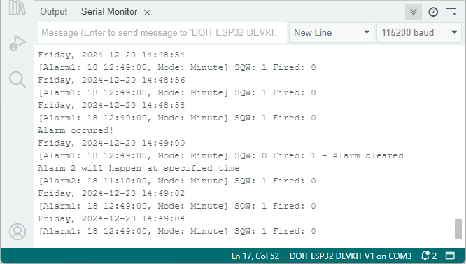
loop() 里每两秒打印一次闹钟 1 的设定时间和当前模式,rtc.alarmFired(1) 为真就清标志、接着设闹钟 2。上传后看串口监视器,闹钟触发时能看到提示并且板载 LED 状态翻转。
写在最后
把这两段程序跑通,DS3231 的三大核心用法就都齐了:I2C 读时间、电池掉电走时、闹钟输出中断。往项目里嫁接也容易,比如配一个时控开关做定时喂食,或者在闹钟中断里让 ESP32 从 deep sleep 醒来采一次传感器数据再睡回去,电池供电的设备续航能拉长不少。
给新手的三句提醒:电池一定要用 LIR2032 或者按前面说的断开充电电路;闹钟标志用完要清;改闹钟时间就改 DateTime 那两行,格式是年、月、日、时、分、秒。照着这篇做,遇到 RTC 找不到的情况,先查线再跑 I2C 扫描,八成是 SDA、SCL 接反了。




照着第一段代码跑通了,串口 115200 记得别选错,否则就是一堆乱码。温度那个 getTemperature 还挺准,和室温计差不到一度
SQW 引脚能触发 deep sleep 唤醒这个点很实用,比定时器唤醒省事多了, mark 一下周末试试
正好在做一个温室数据记录的小东西,MX 卡的就是断电时间归零,看完这篇直接下单了一块模块
这个电池的坑我必须补一句:我当年图便宜买了 CR2032 直接插上去用,当时看是正常的,其实模块上的充电电路一直在给不可充电的锂锰电池充电,时间长了有鼓包漏液的风险。后来照着教程把二极管旁边那颗限流电阻焊掉了才安心。要么就老老实实买 LIR2032,几块钱的事,别在这一步省。另外提醒一句,焊掉电阻后充电回路就断了,换电池也不会有问题,这个改法是不可逆的,动手前想清楚。