
想给机器人或门禁加一套刷卡识别,PN532 是绕不开的芯片。它是 NXP 出的近场通信控制器,支持 13.56MHz 频段的读卡与写卡,Mifare Classic、Mifare Ultralight 这类常见的 IC 卡都能打交道。Adafruit 的 PN532 扩展板是这颗芯片最经典的落地形态,官方学习系统上有完整的接线图、库和例程,照着做基本不会翻车。
这篇把流程理成一条线:认识模块与三种通信模式、接 Uno、装库、读卡 UID、写数据块,最后讲讲做门禁卡识别时的几个常见坑。全程以 Adafruit 官方教程为底稿,代码逐字符搬自官方例程,照抄即可跑。
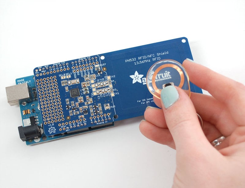
先认模块:PN532 与三档通信模式
PN532 扩展板自己不带主控,它只是给 PN532 芯片搭好了外围电路,通过接口与 Arduino 通信。板子边缘有三个关键的焊盘:SEL0、SEL1,这两个接口选择器决定芯片用哪种方式说话。插上不同位置的跳线帽,通信协议就不同,这一点是新手最容易栽的地方。
三种模式的取舍,按使用场景排一排:
1. HSU(高速 UART):只占两个引脚,最省资源,适合引脚紧张的小板,串口直连即可,但对软串口的波特率稳定性有要求。
2. I2C:占 SDA、SCL 加 IRQ、RESET,可与其他 I2C 器件共享总线,引脚开销适中,Uno 上接 A4、A5 两条模拟口线。
3. SPI:速度最快,官方教程演示 SPI 档时要求 SEL1 跳线拨到 ON、SEL0 拨到 OFF;软 SPI 只占 4 个普通数字脚,硬 SPI 则要落到 Uno 的 13、11、12 脚上。三档怎么拨,每块板的丝印上都印了对应组合,照丝印拨即可,拿不准就先拨 SPI 档跑官方例程。
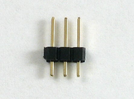
提醒一句:三档模式的跳线拨错,模块不会有任何报错,现象只是库怎么都找不到芯片。所以上电之前先确认跳线位置和代码里的构造函数选的是同一种模式,这是省下半小时调试的第一要诀。
接线:扩展板与 Uno 的连接
PN532 芯片本体是 3.3V 器件,接到 5V 系统如 Arduino 时需要电平转换。Adafruit 的扩展板已经在板上集成了 4050 电平转换芯片,Arduino 侧可以放心接 5V 逻辑,但供电要接 3.3V——官方接线图里红色电源线明确要求接在 Arduino 的 3.3V 引脚上。
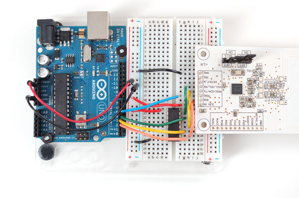
按官方 SPI 接线图走线:SCK 接 Arduino 数字脚 2,MOSI 接数字脚 3,SSEL 接数字脚 4,MISO 接数字脚 5,这是软 SPI 的引脚组合;GND 接地,3.3Vin 接 Arduino 的 3.3V。Uno 的数字脚 2、3、4、5 都在这里被用掉,如果后面还要接其他器件,注意预留。跳线拨 SPI 档(SEL1 为 ON、SEL0 为 OFF)之后,硬件部分就绪。
装库与上电自检
到 Arduino IDE 的库管理器里搜 Adafruit PN532 安装即可,官方库托管在 GitHub 的 adafruit/Adafruit-PN532 仓库。例程里的 readMifare.ino 是读卡最典型的一个,下面这段完整代码逐字符搬自官方例程,只把尖括号头文件改成了引号写法:
#include "Wire.h"
#include "SPI.h"
#include "Adafruit_PN532.h"

// If using the breakout with SPI, define the pins for SPI communication.
#define PN532_SCK  (2)
#define PN532_MOSI (3)
#define PN532_SS   (4)
#define PN532_MISO (5)

// If using the breakout or shield with I2C, define just the pins connected
// to the IRQ and reset lines.  Use the values below (2, 3) for the shield!
#define PN532_IRQ   (2)
#define PN532_RESET (3)  // Not connected by default on the NFC Shield

// Uncomment just _one_ line below depending on how your breakout or shield
// is connected to the Arduino:

// Use this line for a breakout with a software SPI connection (recommended):
Adafruit_PN532 nfc(PN532_SCK, PN532_MISO, PN532_MOSI, PN532_SS);

// Use this line for a breakout with a hardware SPI connection.  Note that
// the PN532 SCK, MOSI, and MISO pins need to be connected to the Arduino's
// hardware SPI SCK, MOSI, and MISO pins.  On an Arduino Uno these are
// SCK = 13, MOSI = 11, MISO = 12.  The SS line can be any digital IO pin.
//Adafruit_PN532 nfc(PN532_SS);

// Or use this line for a breakout or shield with an I2C connection:
//Adafruit_PN532 nfc(PN532_IRQ, PN532_RESET);

void setup(void) {
  Serial.begin(115200);
  while (!Serial) delay(10); // for Leonardo/Micro/Zero

  Serial.println("Hello!");

  nfc.begin();

  uint32_t versiondata = nfc.getFirmwareVersion();
  if (! versiondata) {
    Serial.print("Didn't find PN53x board");
    while (1); // halt
  }
  // Got ok data, print it out!
  Serial.print("Found chip PN5"); Serial.println((versiondata>>24) & 0xFF, HEX);
  Serial.print("Firmware ver. "); Serial.print((versiondata>>16) & 0xFF, DEC);
  Serial.print('.'); Serial.println((versiondata>>8) & 0xFF, DEC);

  Serial.println("Waiting for an ISO14443A Card ...");
}

void loop(void) {
  uint8_t success;
  uint8_t uid[] = { 0, 0, 0, 0, 0, 0, 0 };  // Buffer to store the returned UID
  uint8_t uidLength;                        // Length of the UID (4 or 7 bytes depending on ISO14443A card type)

  // Wait for an ISO14443A type cards (Mifare, etc.).  When one is found
  // 'uid' will be populated with the UID, and uidLength will indicate
  // if the uid is 4 bytes (Mifare Classic) or 7 bytes (Mifare Ultralight)
  success = nfc.readPassiveTargetID(PN532_MIFARE_ISO14443A, uid, &uidLength);

  if (success) {
    // Display some basic information about the card
    Serial.println("Found an ISO14443A card");
    Serial.print("  UID Length: ");Serial.print(uidLength, DEC);Serial.println(" bytes");
    Serial.print("  UID Value: ");
    nfc.PrintHex(uid, uidLength);
    Serial.println("");

    if (uidLength == 4)
    {
      // We probably have a Mifare Classic card ...
      Serial.println("Seems to be a Mifare Classic card (4 byte UID)");

      // Now we need to try to authenticate it for read/write access
      // Try with the factory default KeyA: 0xFF 0xFF 0xFF 0xFF 0xFF 0xFF
      Serial.println("Trying to authenticate block 4 with default KEYA value");
      uint8_t keya[6] = { 0xFF, 0xFF, 0xFF, 0xFF, 0xFF, 0xFF };

      // Start with block 4 (the first block of sector 1) since sector 0
      // contains the manufacturer data and it's probably better just
      // to leave it alone unless you know what you're doing
      success = nfc.mifareclassic_AuthenticateBlock(uid, uidLength, 4, 0, keya);

      if (success)
      {
        Serial.println("Sector 1 (Blocks 4..7) has been authenticated");
        uint8_t data[16];

        // If you want to write something to block 4 to test with, uncomment
        // the following line and this text should be read back in a minute
        //memcpy(data, (const uint8_t[]){ 'a', 'd', 'a', 'f', 'r', 'u', 'i', 't', '.', 'c', 'o', 'm', 0, 0, 0, 0 }, sizeof data);
        // success = nfc.mifareclassic_WriteDataBlock (4, data);

        // Try to read the contents of block 4
        success = nfc.mifareclassic_ReadDataBlock(4, data);

        if (success)
        {
          // Data seems to have been read ... spit it out
          Serial.println("Reading Block 4:");
          nfc.PrintHexChar(data, 16);
          Serial.println("");

          // Wait a bit before reading the card again
          delay(1000);
        }
        else
        {
          Serial.println("Ooops ... unable to read the requested block.  Try another key?");
        }
      }
      else
      {
        Serial.println("Ooops ... authentication failed: Try another key?");
      }
    }

    if (uidLength == 7)
    {
      // We probably have a Mifare Ultralight card ...
      Serial.println("Seems to be a Mifare Ultralight tag (7 byte UID)");

      // Try to read the first general-purpose user page (#4)
      Serial.println("Reading page 4");
      uint8_t data[32];
      success = nfc.mifareultralight_ReadPage (4, data);
      if (success)
      {
        // Data seems to have been read ... spit it out
        nfc.PrintHexChar(data, 4);
        Serial.println("");

        // Wait a bit before reading the card again
        delay(1000);
      }
      else
      {
        Serial.println("Ooops ... unable to read the requested page!?");
      }
    }
  }
}
烧录后打开串口监视器,波特率设 115200。模块被正确识别时,会先打印出芯片型号与固件版本,比如 Found chip PN5 与 Firmware ver. 1.6 这类字样;拿一张 Mifare 卡靠近天线区域,UID 会以十六进制打印出来,4 字节 UID 的卡会被判定为 Mifare Classic,7 字节的则按 Mifare Ultralight 走分页读取。
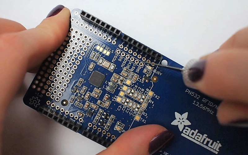
Shield 版则更省事,直接插在 Uno 上,跳线拨到 I2C 档,代码里换成 Adafruit_PN532 nfc(PN532_IRQ, PN532_RESET) 这一行构造函数即可,IRQ 接数字脚 2、RESET 接数字脚 3。
读卡之后:写一个数据块
Mifare Classic 1K 卡有 16 个扇区,每扇区 4 个块,每块 16 字节。每个扇区的最后一个块是块尾(Sector Trailer),存着密钥 A、访问位与密钥 B,各 6 字节密钥;扇区里真正能拿来存数据的,只有前面 3 个块,也就是每个 64 字节扇区里 48 字节归你用。出厂默认密钥 A、B 都是 6 个 0xFF。
写块的动作官方例程里已经备好了,就是上面代码中被注释掉的那两行:去掉行首注释,用 memcpy 把 16 字节数组填好,再调用 mifareclassic_WriteDataBlock 写入块 4,下一轮 loop 读回来就能看到写进去的内容。认证、写、读的流程与读块完全一致,只是把读函数换成写函数。
两个红线必须说在前面:块 0 是厂商块,存着卡的 UID 与厂商数据,官方例程刻意从块 4(扇区 1 的第一个块)开始动,扇区 0 不要碰;写块尾更危险,密钥 A、访问位、密钥 B 一旦写错,整个扇区可能永久锁死。往块尾写任何东西之前,先把密钥和访问位的规则弄明白。
做门禁识别与几个常见的坑
拿来做门禁卡识别,最省事的做法就是读 UID 做白名单比对:把授权卡的 UID 存进数组或 EEPROM,读到的 UID 与之一致就触发开门。要提醒的是,Mifare Classic 的 4 字节 UID 是可以读取的,但不少小区卡与工卡用了加密扇区,直接对扇区认证会失败——例程里那句 authentication failed 后面跟着的 Try another key 提示,说的就是这个场景,换个已知密钥再试。
常见的坑按出现频率排:一是模式跳线拨错,前面说过,库找不到芯片第一件事就是核对 SEL0、SEL1 与构造函数;二是供电,模块必须吃 3.3V,直接怼 5V 有烧芯片的风险,接线图里 4050 电平转换芯片的 1 脚接 3.3V、8 脚接地也要照做;三是串口波特率,例程固定 115200,监视器没对上就只见乱码;四是天线距离,卡片要贴到天线区域 1 厘米以内,隔太远 readPassiveTargetID 会一直返回失败。
整套流程跑通之后,读 UID、认证、读写数据块这三个动作就齐了,往门禁、储物柜、签到打卡这类应用上套,剩下的是业务逻辑的活。PN532 库里还有 NDEF 格式化、整卡 dump 等例程,想深挖的话,官方库的 examples 目录值得整个翻一遍。


收藏了,正好打算给楼下储物柜做个刷卡开门。
PN532 比 RC522 贵不少,但支持的模式多,还能当卡模拟,值得。
默认密钥 FFFFFFFFFFFF 那段太真实了,第一次写块尾没备份,扇区直接锁死,一张卡报废。新手千万别碰块 3 和块 0。
这篇把我上次折腾两天的坑基本都踩中了:SEL0/SEL1 跳线拨成 I2C 档但代码里用了软 SPI 的构造函数,串口死活只打印 Didn't find PN53x board。后来照丝印重新对了一遍才通。补充一点,某宝买的紫色 PN532 小模块和 Adafruit 这块扩展板丝印不一样,那个是 DIP 开关,HSU 档两个都拨 ON,接 Uno 用软串口也挺好使,省四个脚。