
给 Arduino 项目加数字输入,第一个念头往往是一排按键。可真要输入一串数字,比如做个密码面板,七八个按键每个都要占一个数字引脚,再加上接地,UNO 的引脚很快就见底了。给每个键配一个输入口,接线翻倍、代码变长,最后还是不够用,这是独立按键方案绕不开的三道坎。常见的替代路子有两条:一是电阻键盘,把一串按键接进电阻分压阵列,只吃一个模拟口,靠 ADC 读出的电压区分键位,键一多就受基准电压漂移和电阻误差折磨;二是串口接整块键盘,功能最强但为输个密码属于杀鸡用牛刀。薄膜矩阵键盘卡在中间,正好合适:16 个键只吃 8 根线,几十块钱以内就能拿下,是创客套件里的常客。这篇把它讲透:行列扫描为什么省线、怎么接线、Keypad 库怎么用,最后搭一个能驱动继电器的密码锁。
16 个键为什么只用 8 根线:行列扫描原理
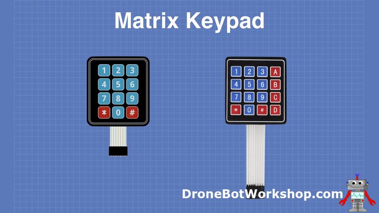
常见的薄膜矩阵键盘有两种规格,4x3(12 键)和 4x4(16 键),排布和电话拨号盘一样。4x4 键盘背后是 4 条行线加 4 条列线,16 个轻触开关每个都跨接在一条行线和一条列线的交叉点上,按下即把这条行线和这条列线接通。行线加列线一共 8 根,比 16 个独立按键省了一半接线;键位越多省得越多。
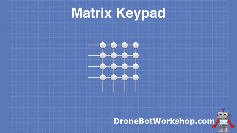
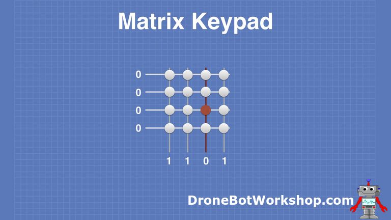
扫描的套路分两步。第一步测列:列线全部配成输入并拉高,行线全部配成输出置低。此时没有键按下,所有列线保持高电平;一旦某键按下,它所在的列线就被行线的低电平拉低,由此锁定列号,同时也确认了确实有键按下。第二步测行:把所有列线拉低,再逐条把行线拉高,哪条行线抬高时被按住的那根列线跟着变高,行号就出来了。行号乘上列号,键位确定,整个过程几微秒就跑完一轮。
8 针排线怎么接:R1 到 R4、C1 到 C4
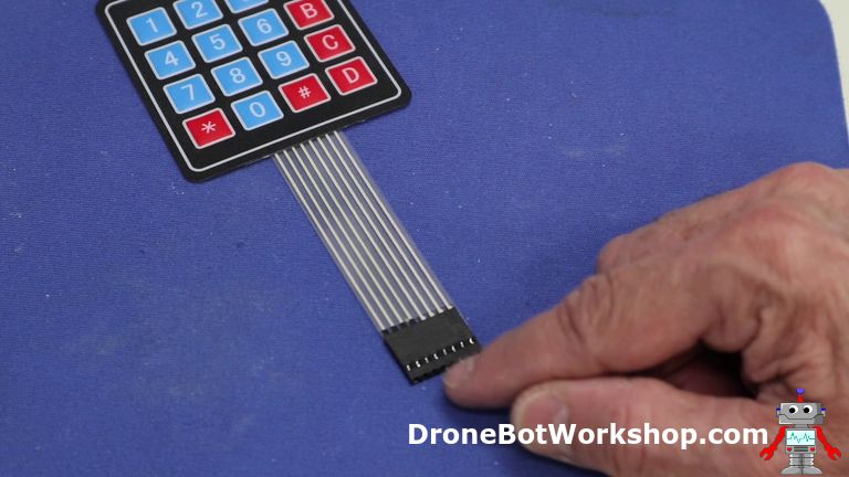
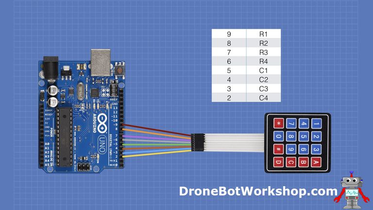
薄膜键盘的两条排线最后汇成一个 8 针母头 Dupont 连接器,从左到右依次是 R1、R2、R3、R4、C1、C2、C3、C4,也就是行 1 到行 4、列 1 到列 4。手头若是 4x3 款,连接器只有 7 针,少的正是 C4,接法和代码只需把列数改成 3。
接到 UNO 最省事的办法是用一条 8 芯公对母 Dupont 排线,一遍插过去,顺序都不用打乱。按原教程的接法,键盘 R1 到 R4 依次接 D9、D8、D7、D6,C1 到 C4 依次接 D5、D4、D3、D2。这张引脚表和后面代码里的两个数组一一对应,接线时对着表插,错一根就会读到错乱的键值。
Keypad 库:十几行代码读完全部按键
行列扫描听起来步骤不少,但不用自己写扫描例程。Keypad 库(作者 Mark Stanley 和 Alexander Brevig)把两步扫描和去抖全部封装好了,在库管理器里搜 keypad 装上即可。先做最小验证:接好线,烧下面的测试程序,开串口监视器把波特率拨到 9600,挨个按一遍 16 个键,屏幕上应逐个冒出对应的字符。哪个键没反应或串出别的键值,回头查那一根线。
/*
  Matrix Keypad Demo
  keypad-demo.ino
  Demonstrates use of 4x4 matrix membrane keypad with Arduino
  Results on serial monitor

  DroneBot Workshop 2020
  https://dronebotworkshop.com
*/

// Include the Keypad library
#include "Keypad.h"

// Constants for row and column sizes
const byte ROWS = 4;
const byte COLS = 4;

// Array to represent keys on keypad
char hexaKeys[ROWS][COLS] = {
  {'1', '2', '3', 'A'},
  {'4', '5', '6', 'B'},
  {'7', '8', '9', 'C'},
  {'*', '0', '#', 'D'}
};

// Connections to Arduino
byte rowPins[ROWS] = {9, 8, 7, 6};
byte colPins[COLS] = {5, 4, 3, 2};

// Create keypad object
Keypad customKeypad = Keypad(makeKeymap(hexaKeys), rowPins, colPins, ROWS, COLS);

void setup() {
  // Setup serial monitor
  Serial.begin(9600);
}

void loop() {
  // Get key value if pressed
  char customKey = customKeypad.getKey();

  if (customKey) {
    // Print key value to serial monitor
    Serial.println(customKey);
  }
}
代码结构是三样东西:hexaKeys 二维数组描述键位布局,rowPins 和 colPins 两个数组声明行线列线各接在哪个引脚,最后把三者交给 Keypad 构造函数建出 keypad 对象。loop 里 getKey() 有按键时返回字符,没有就返回 0,拿去串口打印就行。换 4x3 键盘时改 ROWS、COLS 和键位数组三处即可,引脚数组同步缩短。
接上 LCD1602:按键回显到屏幕
串口验证通过后,把显示搬到 I2C 背包版 LCD1602 上,这是键盘类项目最常见的搭配,输入密码时屏幕能逐位回显。I2C 版只占 A4、A5 两个模拟口:GND 对 GND,VCC 接 5V,SDA 接 A4,SCL 接 A5。
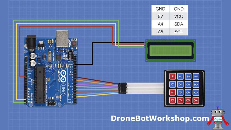
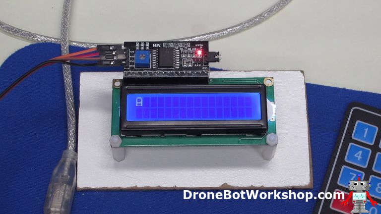
驱动这块屏要用 LiquidCrystal_I2C 库。注意这个库不在库管理器里,得去 GitHub 下 ZIP 包,再用 IDE 的“项目-导入库-添加 .ZIP 库”装进去。装好后烧下面的程序,屏幕地址参数 0x3F 是最常见的 PCF8574 背包地址,个别模块是 0x27,扫不到字符先查这个值;屏幕背光亮着但没字,拧背包上的蓝色电位器。
/*
  Matrix Keypad with LCD Display Demo
  keypad-demo-lcd.ino
  Demonstrates use of 4x4 matrix membrane keypad with Arduino
  Results on LCD Display
  Display uses I2C backpack

  DroneBot Workshop 2020
  https://dronebotworkshop.com
*/

// Include Arduino Wire library for I2C
#include "Wire.h"
// Include LCD display library for I2C
#include "LiquidCrystal_I2C.h"
// Include Keypad library
#include "Keypad.h"

// Constants for row and column sizes
const byte ROWS = 4;
const byte COLS = 4;

// Array to represent keys on keypad
char hexaKeys[ROWS][COLS] = {
  {'1', '2', '3', 'A'},
  {'4', '5', '6', 'B'},
  {'7', '8', '9', 'C'},
  {'*', '0', '#', 'D'}
};

// Connections to Arduino
byte rowPins[ROWS] = {9, 8, 7, 6};
byte colPins[COLS] = {5, 4, 3, 2};

// Create keypad object
Keypad customKeypad = Keypad(makeKeymap(hexaKeys), rowPins, colPins, ROWS, COLS);

// Create LCD object
LiquidCrystal_I2C lcd(0x3F, 16, 2);

void setup(){
  // Setup LCD with backlight and initialize
  lcd.backlight();
  lcd.init();
}

void loop(){
  // Get key value if pressed
  char customKey = customKeypad.getKey();

  if (customKey){
    // Clear LCD display and print character
    lcd.clear();
    lcd.setCursor(0, 0);
    lcd.print(customKey);
  }
}
和串口版相比,loop 里只把打印目标从 Serial 换成了 lcd:每检测到一次按键就清屏、光标回原点、打印字符,字符会一直停在屏上直到下一个键按下。
实战:驱动继电器的密码锁
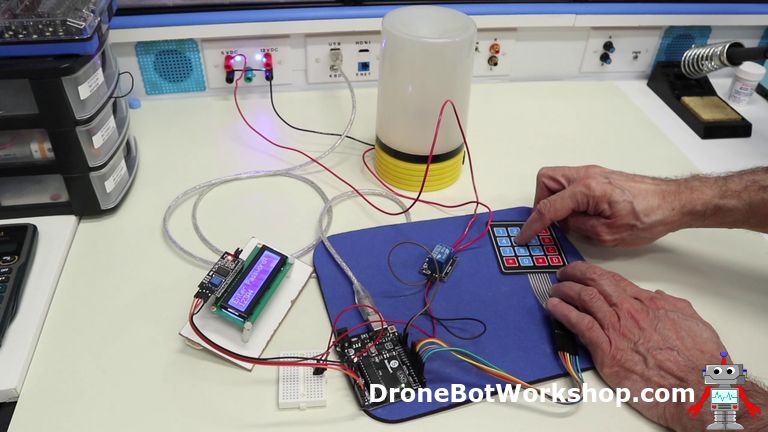
硬件不动大架,只加一个继电器模块,就是一版能用的密码锁。原教程用它驱动电磁锁,演示时接的是一盏台灯,看得更直观。继电器模块三个输入端:GND、VCC(5V)和触发端 IN,IN 接 D13——这脚带着板载 LED,继电器不动的时候先看灯闪不闪,排查方便。电磁锁这类负载通常 12V 供电,接在继电器输出端的 COM 和 NO 之间,通电即释放锁舌;通电时间过长容易烧线圈,吸合几秒足够开门,具体回去翻锁的规格书。
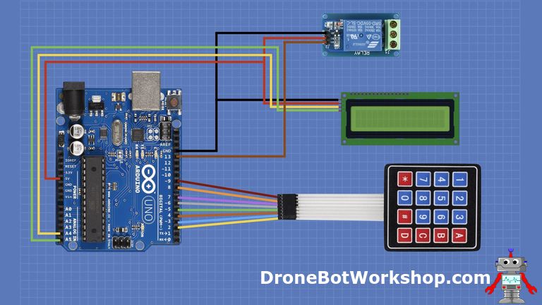
锁的逻辑:屏幕提示输入密码,逐位回显,输满 7 位自动比对,正确则继电器吸合 5 秒后释放,错误则显示 Incorrect 一秒,随后清屏清数组等下一次输入。继电器输出端三个端子各有分工:COM 是公共端,NO 常开、NC 常闭;电磁锁这类负载接在电源正极与 COM 之间、经 NO 回电源负极,继电器一吸合就构成回路。通电时间过长容易烧线圈,吸合几秒足够开门,具体回去翻锁的规格书。密码存在 Master 数组里,记得换成自己的组合;Password_Length 定义的是密码位数加 1(给字符串结尾的 null 留位),改密码长度时两处要一起动。
/*
  Matrix Keypad Combination Lock Demo
  keypad-demo-lock.ino
  Combination lock using 4x4 matrix membrane keypad with Arduino
  Results on LCD display
  Drives relay

  DroneBot Workshop 2020
  https://dronebotworkshop.com

  Based upon code from https://www.circuitbasics.com/

*/

// Include Arduino Wire library for I2C
#include "Wire.h"
// Include LCD display library for I2C
#include "LiquidCrystal_I2C.h"
// Include Keypad library
#include "Keypad.h"

// Length of password + 1 for null character
#define Password_Length 8
// Character to hold password input
char Data[Password_Length];
// Password
char Master[Password_Length] = "123A456";

// Pin connected to lock relay input
int lockOutput = 13;

// Counter for character entries
byte data_count = 0;

// Character to hold key input
char customKey;

// Constants for row and column sizes
const byte ROWS = 4;
const byte COLS = 4;

// Array to represent keys on keypad
char hexaKeys[ROWS][COLS] = {
  {'1', '2', '3', 'A'},
  {'4', '5', '6', 'B'},
  {'7', '8', '9', 'C'},
  {'*', '0', '#', 'D'}
};

// Connections to Arduino
byte rowPins[ROWS] = {9, 8, 7, 6};
byte colPins[COLS] = {5, 4, 3, 2};

// Create keypad object
Keypad customKeypad = Keypad(makeKeymap(hexaKeys), rowPins, colPins, ROWS, COLS);

// Create LCD object
LiquidCrystal_I2C lcd(0x3F, 16, 2);

void setup() {
  // Setup LCD with backlight and initialize
  lcd.backlight();
  lcd.init();

  // Set lockOutput as an OUTPUT pin
  pinMode(lockOutput, OUTPUT);
}

void loop() {

  // Initialize LCD and print
  lcd.setCursor(0, 0);
  lcd.print("Enter Password:");

  // Look for keypress
  customKey = customKeypad.getKey();
  if (customKey) {
    // Enter keypress into array and increment counter
    Data[data_count] = customKey;
    lcd.setCursor(data_count, 1);
    lcd.print(Data[data_count]);
    data_count++;
  }

  // See if we have reached the password length
  if (data_count == Password_Length - 1) {
    lcd.clear();

    if (!strcmp(Data, Master)) {
      // Password is correct
      lcd.print("Correct");
      // Turn on relay for 5 seconds
      digitalWrite(lockOutput, HIGH);
      delay(5000);
      digitalWrite(lockOutput, LOW);
    }
    else {
      // Password is incorrect
      lcd.print("Incorrect");
      delay(1000);
    }

    // Clear data and LCD display
    lcd.clear();
    clearData();
  }
}

void clearData() {
  // Go through array and clear data
  while (data_count != 0) {
    Data[data_count--] = 0;
  }
  return;
}
最后给三条边界,都是决定用不用矩阵键盘前该想的。一是规模:按键少于 6 个时矩阵不划算,2x3 矩阵要 5 根线,独立按键反而更省;超过 25 键则不如直接上串口键盘方案。二是交互:矩阵键盘一次只认一个键,需要组合键的场景别用它。三是排错次序:键值乱跳先查接线顺序对不对得上 rowPins、colPins 两个数组,屏不亮先查 I2C 地址和电位器,库装不上把 IDE 的报错贴出来看,多半是 ZIP 包套了一层文件夹。把这三条记住,4x4 薄膜键盘基本不会再给你添堵。


上个月刚给车库门禁换了套方案,用的就是4x4薄膜键盘加I2C屏,这篇的行列扫描讲得比我当年啃的资料清楚多了。特别认同结尾那条排错次序:我第一次接线就是R3和C2插反,按键读出来全是乱码,对着rowPins数组查了两遍才抓出来。另外提醒一句,那种带蓝色贴膜的键盘用久了膜会翘边,撕掉贴膜的手感反而更脆。
getKey()不用delay轮询这点太省心了,配合OLED做设置菜单比按键堆引脚舒服多了
8芯排线一遍插过去这个思路好,我当年一根根杜邦线插错三次
0x3F这个地址提醒到位,我手上有块屏就是0x27,扫不到字符来回折腾半天,最后i2cdetect一扫才明白