
给 ESP32 做远程控制,方案不止一种,但要说数据收发两边都清爽的,MQTT 是绕不开的那一条路。这篇基于 Random Nerd Tutorials 的 ESP32 MQTT 教程整理:ESP32 用 PubSubClient 库连 Mosquitto broker,一边把 BME280 的温湿度读数发出去,一边订阅主题接收指令控制 LED。全流程的代码和参数都对着底稿核过,值直接可以照抄。
先把账算清:MQTT 到底怎么运转
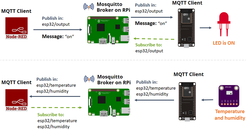
MQTT 是典型的发布/订阅模型,所有消息都要经过一个中间人——broker。谁想收消息就先向 broker 订阅某个主题(topic),谁想发消息就往主题上发布,发布方和订阅方互相不见面,全靠 broker 分发。这篇教程里的 broker 是装在树莓派上的 Mosquitto,同一块树莓派上还跑着一个 Node-RED 应用做控制面板。
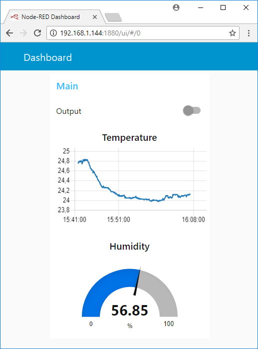
消息流向看着很对称:Node-RED 往 esp32/output 主题发布 "on" 或 "off",ESP32 订阅了这个主题,收到指令就开关接在 GPIO 4 上的 LED;反过来,ESP32 把温度发到 esp32/temperature、湿度发到 esp32/humidity,Node-RED 订阅这两个主题,把读数画成曲线和仪表盘。一张图把两条链路看全。
准备工作:一个库、一组接线
ESP32 侧要用的是 PubSubClient 库,GitHub 上 knolleary/pubsubclient 仓库维护,作者 Nick O'Leary 本身就是 Node-RED 的核心开发者,和这套方案天然配套。安装走 zip 路线:从 GitHub 下载 master.zip,解压得到 pubsubclient-master 文件夹,把名字改成 pubsubclient,挪进 Arduino IDE 的 libraries 目录,重开 IDE 就能在 File > Examples > PubSubClient 里看到自带示例。底稿里有一句值得记住的提醒:PubSubClient 对 ESP32 的兼容并不完整,但教程给的这套示例在作者的测试里跑得非常稳。
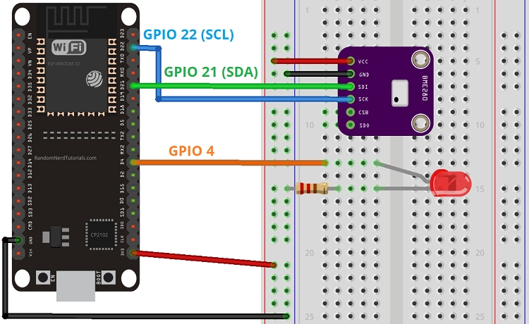
电路不复杂,两块内容。BME280 走 I2C:SDA 接 GPIO 21,SCL 接 GPIO 22,模块供电接 3.3V;代码里传感器地址写的是 0x76。LED 接 GPIO 4,串一个限流电阻到地即可。接线对照下图核一遍再上电。
完整代码:发布和订阅各管一半
上传前要改三处:ssid、password 换成自己的 WiFi,mqtt_server 换成 broker 的 IP 地址(底稿示例是 192.168.1.144 这个网段的局域网地址)。代码贴在下面,唯一改动是把尖括号头文件写成了引号形式,两种写法在 Arduino 工具链下编译等价,只是站点编辑器会剥掉尖括号写法,其余一个字符没动。
/*********
  Rui Santos
  Complete project details at https://randomnerdtutorials.com
*********/

#include "WiFi.h"
#include "PubSubClient.h"
#include "Wire.h"
#include "Adafruit_BME280.h"
#include "Adafruit_Sensor.h"

// Replace the next variables with your SSID/Password combination
const char* ssid = "REPLACE_WITH_YOUR_SSID";
const char* password = "REPLACE_WITH_YOUR_PASSWORD";

// Add your MQTT Broker IP address, example:
//const char* mqtt_server = "192.168.1.144";
const char* mqtt_server = "YOUR_MQTT_BROKER_IP_ADDRESS";

WiFiClient espClient;
PubSubClient client(espClient);
long lastMsg = 0;
char msg[50];
int value = 0;

//uncomment the following lines if you're using SPI
/*#include "SPI.h"
#define BME_SCK 18
#define BME_MISO 19
#define BME_MOSI 23
#define BME_CS 5*/

Adafruit_BME280 bme; // I2C
//Adafruit_BME280 bme(BME_CS); // hardware SPI
//Adafruit_BME280 bme(BME_CS, BME_MOSI, BME_MISO, BME_SCK); // software SPI
float temperature = 0;
float humidity = 0;

// LED Pin
const int ledPin = 4;

void setup() {
  Serial.begin(115200);
  // default settings
  // (you can also pass in a Wire library object like &Wire2)
  //status = bme.begin();
  if (!bme.begin(0x76)) {
    Serial.println("Could not find a valid BME280 sensor, check wiring!");
    while (1);
  }
  setup_wifi();
  client.setServer(mqtt_server, 1883);
  client.setCallback(callback);

  pinMode(ledPin, OUTPUT);
}

void setup_wifi() {
  delay(10);
  // We start by connecting to a WiFi network
  Serial.println();
  Serial.print("Connecting to ");
  Serial.println(ssid);

  WiFi.begin(ssid, password);

  while (WiFi.status() != WL_CONNECTED) {
    delay(500);
    Serial.print(".");
  }

  Serial.println("");
  Serial.println("WiFi connected");
  Serial.println("IP address: ");
  Serial.println(WiFi.localIP());
}

void callback(char* topic, byte* message, unsigned int length) {
  Serial.print("Message arrived on topic: ");
  Serial.print(topic);
  Serial.print(". Message: ");
  String messageTemp;

  for (int i = 0; i < length; i++) {
    Serial.print((char)message[i]);
    messageTemp += (char)message[i];
  }
  Serial.println();

  // Feel free to add more if statements to control more GPIOs with MQTT

  // If a message is received on the topic esp32/output, you check if the message is either "on" or "off".
  // Changes the output state according to the message
  if (String(topic) == "esp32/output") {
    Serial.print("Changing output to ");
    if(messageTemp == "on"){
      Serial.println("on");
      digitalWrite(ledPin, HIGH);
    }
    else if(messageTemp == "off"){
      Serial.println("off");
      digitalWrite(ledPin, LOW);
    }
  }
}

void reconnect() {
  // Loop until we're reconnected
  while (!client.connected()) {
    Serial.print("Attempting MQTT connection...");
    // Attempt to connect
    if (client.connect("ESP8266Client")) {
      Serial.println("connected");
      // Subscribe
      client.subscribe("esp32/output");
    } else {
      Serial.print("failed, rc=");
      Serial.print(client.state());
      Serial.println(" try again in 5 seconds");
      // Wait 5 seconds before retrying
      delay(5000);
    }
  }
}
void loop() {
  if (!client.connected()) {
    reconnect();
  }
  client.loop();

  long now = millis();
  if (now - lastMsg > 5000) {
    lastMsg = now;

    // Temperature in Celsius
    temperature = bme.readTemperature();
    // Uncomment the next line to set temperature in Fahrenheit
    // (and comment the previous temperature line)
    //temperature = 1.8 * bme.readTemperature() + 32; // Temperature in Fahrenheit

    // Convert the value to a char array
    char tempString[8];
    dtostrf(temperature, 1, 2, tempString);
    Serial.print("Temperature: ");
    Serial.println(tempString);
    client.publish("esp32/temperature", tempString);

    humidity = bme.readHumidity();

    // Convert the value to a char array
    char humString[8];
    dtostrf(humidity, 1, 2, humString);
    Serial.print("Humidity: ");
    Serial.println(humString);
    client.publish("esp32/humidity", humString);
  }
}
订阅这一半在 reconnect() 和 callback() 两个函数里。连接成功后订阅 esp32/output;callback 收到消息就比对主题和内容,是 "on" 就把 GPIO 4 拉高,是 "off" 拉低:
client.subscribe("esp32/output");要扩展更多可控引脚,照这个 if 语句往下加分支就行,callback 里的注释也明确提示了这一点。
发布这一半在 loop() 里,每 5000 毫秒执行一轮:读 BME280 的温度和湿度,用 dtostrf 把 float 转成 char 数组,再分别 publish 到 esp32/temperature 和 esp32/humidity。默认发摄氏度,想要华氏度就把代码里那行换算注释打开:
// If a message is received on the topic esp32/output, you check if the message is either "on" or "off".
// Changes the output state according to the message
if (String(topic) == "esp32/output") {
  Serial.print("Changing output to ");
  if (messageTemp == "on") {
    Serial.println("on");
    digitalWrite(ledPin, HIGH);
  }
  else if (messageTemp == "off") {
    Serial.println("off");
    digitalWrite(ledPin, LOW);
  }
}
上传验证与 Node-RED 面板
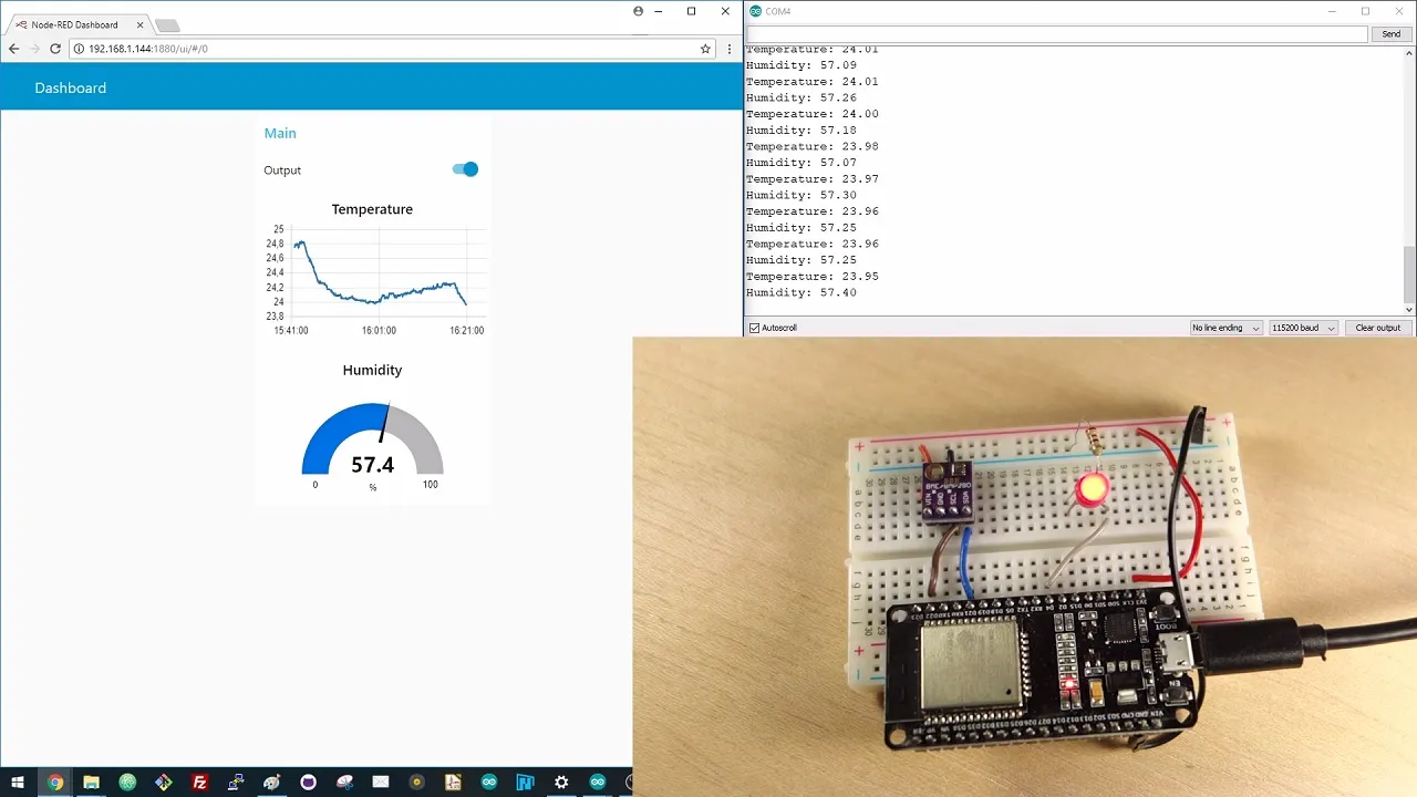
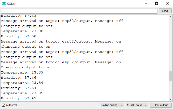
代码烧进去后打开串口监视器,波特率 115200。正常的话每 5 秒刷一组 Temperature 和 Humidity 读数;只要 Node-RED 那边按了开关,就能看到 Message arrived on topic: esp32/output. Message: on/off 和 Changing output to on/off 成对出现,底稿截图里的实测读数在 23.9 摄氏度、57.5% 湿度上下。
树莓派那头要提前装好 Node-RED、Node-RED Dashboard 和 Mosquitto broker 三样。控制面板不用手搭:底稿把整条流程导出成了文件,在它的 GitHub 仓库里能拿到原始内容,Node-RED 菜单里 Import > Clipboard 粘贴进去,节点自动铺开,改完点 Deploy 生效。浏览器打开树莓派 IP 的 1880 端口下的 ui 页面,温度曲线、湿度仪表盘和 Output 开关都在上面。
几个容易踩的坑
- mqtt_server 千万别留着占位符编译,程序会一直走 reconnect 循环,串口反复打印 failed, rc= 加错误码,每 5 秒重试一次。
- client.connect 里客户端名写的是 "ESP8266Client",名字本身不影响功能,但如果两个设备用同一个名字连同一个 broker,会被互相踢,多设备时记得改唯一。
- LED 和传感器都在 3.3V 逻辑下工作,别为了"亮一点"把 LED 直接连到 5V 引脚,GPIO 4 的驱动能力按 3.3V 算。
- PubSubClient 对 ESP32 兼容不完整是底稿明说的,遇到奇怪的断连,先确认库是最新版本,再检查 broker 是否真在 1883 端口监听。
整套方案跑通之后,扩展方向很自然:多加几个主题就能控制更多 GPIO,把 BME280 换成别的传感器,也只是改发布那几行读的值而已。MQTT 这套发布/订阅的骨架定了,剩下的都是往里填内容的事。




之前一直用HTTP轮询拿传感器数据,ESP32每隔几秒请求一次网页,设备多了路由器都扛不住。换成MQTT之后思路完全变了——设备只管往esp32/temperature这种主题上发,谁要数据谁订阅,broker在中间分发,耦合一下就解开了。这篇里GPIO4收on/off指令那段callback写法很标准,比对主题再比对内容,扩展其他引脚照着加if就行。提醒一句broker IP别留占位符编译,不然reconnect里每5秒重试一次,串口一直刷failed rc=,很多人第一次连不上都卡在这。
接线图很清楚,GPIO21 SDA、GPIO22 SCL,BME280地址0x76,照着接没毛病。
Node-RED那套仪表盘是真方便,导入流程文件点Deploy直接能用,省去手搭节点的功夫。
esp32/output上发on和off控制LED,这个设计比发0和1直观多了,排查问题也容易看。
ESP32加MQTT确实是物联网标配组合了,PubSubClient库轻量好用,示例代码拿来就能改。