
想给项目加个"能听见声音"的耳朵,翻资料的时候被一个词卡住了:I2S。模拟声音传感器插上就能读数,这个 INMP441 凭什么要多走一条数字总线的路?后来把 Random Nerd Tutorials 那篇 ESP32 教程从头到尾读了一遍,把接线、代码、踩坑点都理顺了,这篇就照着它的思路,帮同样卡在"数字麦克风"门口的朋友把路铺平。
先搞懂:I2S 是什么,INMP441 强在哪
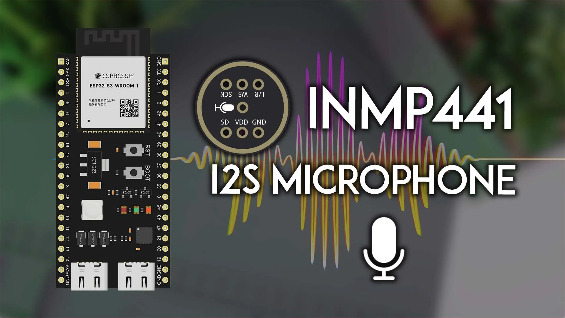
I2S 是一种专门传音频数据的接口标准。通俗点说,普通模拟麦克风给你的是一根随音量起伏的电压线,主板还得自己接 ADC 去量化;而 I2S 麦克风在模块内部就把声音变成了数字信号,用三根线送出来:SCK 是位时钟,WS 是左右声道选择,SD 是串行数据。时钟由主控给,数据按节拍走,抗干扰能力比裸电压强不少。
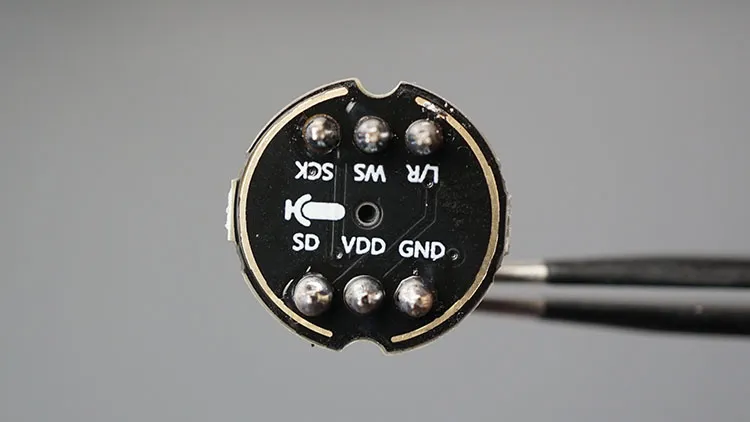
INMP441 本体是一颗 MEMS 全向麦克风,输出 24 位 I2S 数据。模块上一共 6 个引脚:L/R、WS、SCK、SD、VDD、GND。那个 L/R 是声道选择脚,接 GND 时模块工作在左声道,接 VDD 则是右声道。它是 3.3V 器件,供电接 3V3,别接到 5V 上去。
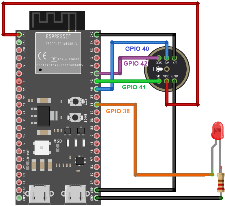
接线:五根线的事
动手前确认 Arduino IDE 里装好了 ESP32 的板子支持。在开发板管理器里搜 esp32 安装 Espressif 官方包,然后板型选你手上的那款,源文用的是 ESP32-S3 开发板。串口波特率统一是 115200,三个例程都一样,监视器里出乱码多半是这里没对上。
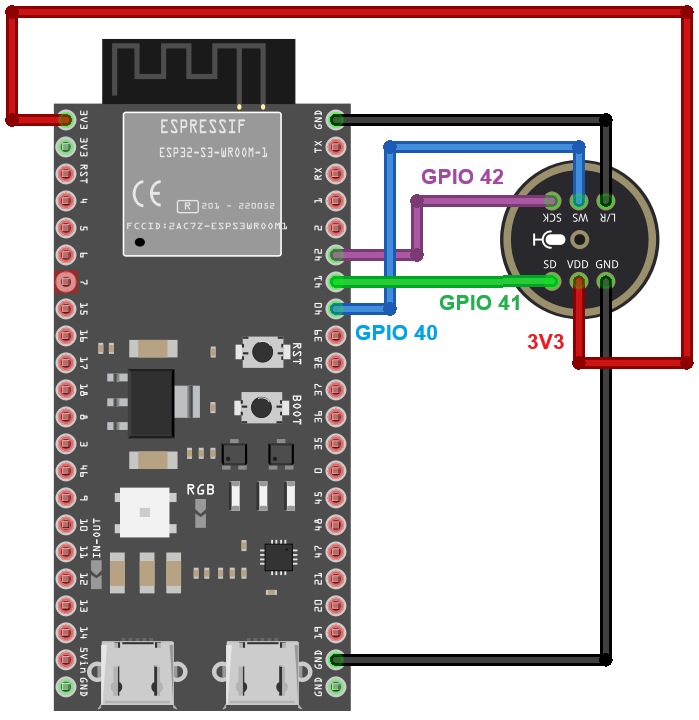
底稿教程用的是 ESP32-S3 开发板,接线如下表。如果你用的是别的 ESP32 型号,GPIO 编号可以换,代码里的宏定义跟着改就行。
| INMP441 引脚 | ESP32-S3 引脚 | 说明 |
|---|---|---|
| VDD | 3V3 | 3.3V 供电 |
| GND | GND | 共地 |
| SCK | GPIO 42 | 位时钟 BCLK |
| WS | GPIO 40 | 声道选择 LRCLK |
| SD | GPIO 41 | 串行数据输入 |
| L/R | GND | 接地选左声道 |
代码方面不用装任何第三方库,ESP32 Arduino 核心自带的 ESP-IDF 驱动头文件直接引就行。原教程代码里 include 用的是尖括号写法,贴进这边的编辑器会被剥掉,下面统一改成引号写法,两种写法在 Arduino 工具链下编译等价,其余代码一个字符都没动。
示例一:算 RMS,把环境声音画成曲线
第一个例子读麦克风,算每个缓冲区里样本的均方根值(RMS),值越大代表当前声音越响。I2S 配成主机接收、16kHz 采样、32 位样本、只用左声道,一次读 512 个样本。有个细节值得记:INMP441 的 24 位数据在 32 位字里是左对齐的,所以代码里要右移 8 位才是真实样本值。
/*
  Rui Santos & Sara Santos - Random Nerd Tutorials
  Complete project details at https://RandomNerdTutorials.com/esp32-inmp441-i2s-microphone-arduino/
  Permission is hereby granted, free of charge, to any person obtaining a copy of this software and associated documentation files.
  The above copyright notice and this permission notice shall be included in all copies or substantial portions of the Software.
*/
#include "driver/i2s.h"

// Pin configuration
#define I2S_SCK   42   // BCLK
#define I2S_WS    40   // LRCLK / WS
#define I2S_SD    41   // DOUT from mic

#define I2S_PORT  I2S_NUM_0
#define SAMPLE_RATE 16000
#define BUFFER_LEN  512

int32_t sBuffer[BUFFER_LEN];

void setup() {
  Serial.begin(115200);
  delay(1000);

  Serial.println("INMP441 Microphone");

  // I2S configuration
  i2s_config_t i2s_config = {
    .mode = (i2s_mode_t)(I2S_MODE_MASTER | I2S_MODE_RX),
    .sample_rate = SAMPLE_RATE,
    .bits_per_sample = I2S_BITS_PER_SAMPLE_32BIT,
    .channel_format = I2S_CHANNEL_FMT_ONLY_LEFT,   // L/R = GND
    .communication_format = I2S_COMM_FORMAT_STAND_I2S,
    .intr_alloc_flags = ESP_INTR_FLAG_LEVEL1,
    .dma_buf_count = 8,
    .dma_buf_len = BUFFER_LEN,
    .use_apll = false
  };

  // Pin configuration
  i2s_pin_config_t pin_config = {
    .bck_io_num = I2S_SCK,
    .ws_io_num = I2S_WS,
    .data_out_num = I2S_PIN_NO_CHANGE,
    .data_in_num = I2S_SD
  };

  // Start I2S
  i2s_driver_install(I2S_PORT, &i2s_config, 0, NULL);
  i2s_set_pin(I2S_PORT, &pin_config);
  i2s_zero_dma_buffer(I2S_PORT);

  Serial.println("I2S started.");
  Serial.println("Reading microphone...");
}

void loop() {
  size_t bytes_read = 0;

  // Read microphone data
  i2s_read(I2S_PORT, sBuffer, sizeof(sBuffer), &bytes_read, portMAX_DELAY);

  int samples_read = bytes_read / sizeof(int32_t);
  double sum = 0;

  // Print the samples
  for (int i = 0; i < samples_read; i++) {

    // INMP441 sends 24-bit audio left-aligned in a 32-bit I2S word
    int32_t sample = sBuffer[i] >> 8;
    //Serial.println(sample);
    sum += (double)sample * sample;
  }
    // Calculate RMS
    double rms = sqrt(sum / samples_read);

    // Print RMS
    //Serial.print("RMS: ");
    Serial.println(rms);
}
为什么用 RMS 而不是直接拿单个样本判断?单个样本抖得厉害,一句话里忽大忽小;RMS 相当于把一小段时间的能量平均了一下,数值稳,拿来做"环境有多吵"的指标正合适。绘图器里的曲线明显比逐样本波形平滑,就是这个道理。
烧录后打开串口监视器只能看到一列数字在跳,切到 Arduino IDE 的串口绘图器(Serial Plotter),就能看到环境噪声的实时曲线了。安静时曲线贴着底部趴着,冲着麦克风说话会鼓起一个大包。
示例二:直接看波形
想看声音本身的形状,把 loop 里的 RMS 计算换成逐样本打印就行。下面这段就是源文里改动的部分,其余与示例一完全相同:
// Print the samples
for (int i = 0; i < samples_read; i++) {

  // INMP441 sends 24-bit audio left-aligned in a 32-bit I2S word
  int32_t sample = sBuffer[i] >> 8;

  Serial.println(sample);
}
再打开串口绘图器,看到的就是一段一段的原始波形,波长对应音调,振幅对应响度。源文还给了个进阶玩法:用 Python 把数据画成图。电脑上装好依赖,把串口数据存下来就能画出更精细的波形图。
pip install pyserial matplotlib示例三:拍两下手,灯就听你的
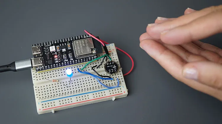
前两个例子是把声音"看"出来,这个例子让声音"干活":检测到双击掌,就翻转一颗 LED 的开关状态。硬件上在原接线之外加一颗 LED:正极接 GPIO 38,负极过电阻接 GND。完整代码如下:
/*
  Rui Santos & Sara Santos - Random Nerd Tutorials
  Complete project details at https://RandomNerdTutorials.com/esp32-inmp441-i2s-microphone-arduino/
  Permission is hereby granted, free of charge, to any person obtaining a copy of this software and associated documentation files.
  The above copyright notice and this permission notice shall be included in all copies or substantial portions of the Software.
*/
#include "driver/i2s.h"

// Pin configuration
#define I2S_SCK   42   // BCLK
#define I2S_WS    40   // LRCLK / WS
#define I2S_SD    41   // DOUT from mic

#define I2S_PORT  I2S_NUM_0
#define SAMPLE_RATE 16000
#define BUFFER_LEN  512

int32_t sBuffer[BUFFER_LEN];

// LED
#define LED_PIN 38

// Clap detection
#define CLAP_THRESHOLD 1000000

// Maximum time allowed between the first and second clap
const unsigned long CLAP_GAP = 700;

// Prevent the same clap from being detected multiple times
const unsigned long CLAP_COOLDOWN = 250;

// State variables
bool ledState = false;

int clapCount = 0;

unsigned long firstClapTime = 0;
unsigned long lastClapTime = 0;

void setup() {
  Serial.begin(115200);
  delay(1000);

  Serial.println("INMP441 Microphone");

  // LED setup
  pinMode(LED_PIN, OUTPUT);
  digitalWrite(LED_PIN, LOW);

  // I2S configuration
  i2s_config_t i2s_config = {
    .mode = (i2s_mode_t)(I2S_MODE_MASTER | I2S_MODE_RX),
    .sample_rate = SAMPLE_RATE,
    .bits_per_sample = I2S_BITS_PER_SAMPLE_32BIT,
    .channel_format = I2S_CHANNEL_FMT_ONLY_LEFT,   // L/R = GND
    .communication_format = I2S_COMM_FORMAT_STAND_I2S,
    .intr_alloc_flags = ESP_INTR_FLAG_LEVEL1,
    .dma_buf_count = 8,
    .dma_buf_len = BUFFER_LEN,
    .use_apll = false
  };

  // Pin configuration
  i2s_pin_config_t pin_config = {
    .bck_io_num = I2S_SCK,
    .ws_io_num = I2S_WS,
    .data_out_num = I2S_PIN_NO_CHANGE,
    .data_in_num = I2S_SD
  };

  // Start I2S
  i2s_driver_install(I2S_PORT, &i2s_config, 0, NULL);
  i2s_set_pin(I2S_PORT, &pin_config);
  i2s_zero_dma_buffer(I2S_PORT);

  Serial.println("I2S started.");
  Serial.println("Double clap to control LED");
}


void loop() {
  size_t bytes_read = 0;

  // Read microphone data
  i2s_read(I2S_PORT, sBuffer, sizeof(sBuffer), &bytes_read, portMAX_DELAY);

  int samples_read = bytes_read / sizeof(int32_t);

  // Find the loudest sample
  int32_t peak = 0;

  // Print the samples
  for (int i = 0; i < samples_read; i++) {
    int32_t sample = sBuffer[i] >> 8;
    int32_t magnitude = abs(sample);

    if (magnitude > peak) {
      peak = magnitude;
    }
  }

  // Print peak
  Serial.println(peak);

  // Detect a clap
  unsigned long now = millis();

  if (peak > CLAP_THRESHOLD && now - lastClapTime > CLAP_COOLDOWN) {
    lastClapTime = now;

    // First clap
    if (clapCount == 0) {
      clapCount = 1;
      firstClapTime = now;
      Serial.println("First clap detected");
    }

    // Second clap
    else if (now - firstClapTime <= CLAP_GAP) {
      clapCount = 0;

      // Double clap - invert LED state
      ledState = !ledState;
      digitalWrite(LED_PIN, ledState);
      if (ledState) {
        Serial.println("DOUBLE CLAP - LED ON");
      }
      else {
        Serial.println("DOUBLE CLAP - LED OFF");
      }
    }

    // Too much time passed
    else {

      // Treat this clap as the beginning of a new pair
      clapCount = 1;
      firstClapTime = now;
      Serial.println("New first clap");
    }
  }

  // Reset if second clap doesn't arrive in time
  if (clapCount == 1 && now - firstClapTime > CLAP_GAP) {
    clapCount = 0;
  }
}
逻辑拆开看不难:每轮循环先找出 512 个样本里的峰值,峰值超过 CLAP_THRESHOLD(1000000)才算一次有效拍手。250 毫秒的冷却期防止同一次拍手被数成两下,700 毫秒的 CLAP_GAP 限制两下之间最多隔多久,超时就把这声当成新一组的第一拍。这套阈值是源文作者实测调出来的,换了房间和麦克风灵敏度后多半要重新调。
调参与延伸:几个能少走弯路的点
阈值是最常见的卡点。建议先把拍手逻辑注释掉,只留打印 peak 那行,对着串口监视器看安静值和拍手值各是多少,再在两者之间取一个有明显余量的数。拍手检测太灵敏,就把阈值调高或把冷却期拉长;拍不响应,先检查是不是阈值定太高、或者人离得太远。
接线复核时重点看三处:L/R 是否真的接地(悬空会导致数据错乱)、VDD 是否接的 3V3、SD 有没有接到 ESP32 的数据输入脚上。I2S 是外设驱动的,普通 GPIO 都能映射,但改了引脚要同步改代码里的三个宏。
把这套东西跑通,后面能玩的方向就多了:接 MAX98357 I2S 功放把声音放出来,做录音回放;把阈值判断换成简单的频谱特征,就能做声控小玩具。源文作者也预告了 MAX98357 的续篇,感兴趣的可以蹲一手。对一个刚搞懂 I2S 是什么的新手来说,这块二十块钱上下的模块,性价比是真的高。

拍手控灯这个例子好玩,CLAP_THRESHOLD 1000000 这个数看着吓人,其实就是 24 位样本的量级,自己调的时候先打印 peak 再定阈值就行。
接线表收藏了,正好手上有块 ESP32-S3 吃灰。
提醒一句新手容易踩的坑:VDD 千万别接 5V,INMP441 是 3.3V 器件,我朋友接 5V 直接烫手了,好在模块没坏。另外串口波特率记得选 115200,不然监视器全是乱码,还以为代码写错了。
这篇把我之前纠结的问题讲明白了。之前一直没想通为什么同一个模块有人接出来全是噪声有人数据很稳,原来关键在那个 L/R 引脚,悬空和接地的行为完全不一样。还有 24 位数据左对齐在 32 位字里这件事,不右移 8 位的话读出来的数全是错的,这种细节网上很多教程都懒得讲,赞一个。
二十块钱买个数字麦克风,比我买的模拟声音传感器稳多了,早看到这篇就好了