
玩 ESP32 的路上,手机控制 LED 差不多是每个人都会撞上的第一个"联网开关"需求。实现方式有好几种,上一期刚聊过 MQTT 那条路,这篇不碰消息服务器,走最朴素的一条:让 ESP32 自己当一台 HTTP 网页服务器,手机浏览器直接输 IP 访问,点按钮开关 LED。整套东西只用到 ESP32 Arduino 核心自带的 WiFi.h,不装任何第三方库,十分钟内能跑通。
这篇整理自 Random Nerd Tutorials 的经典入门教程,代码和接线都按原文逐项核对过,原文里一处排版有瑕疵的注释也顺手理顺了。全文按"硬件准备、接线、烧代码、看 IP、网页控制"的顺序走,照着做就能出结果。
一、先备齐这几样东西
硬件清单很短:一块 ESP32 开发板(教程原文用的是 36 引脚的 ESP32 DEVKIT DOIT)、两个 5mm LED、两个 330Ω 限流电阻,再加一块面包板和几根跳线。都是入门常见件,几乎不需要额外采购。
软件这边只需要 Arduino IDE,并且装好 ESP32 的板卡支持包。板子选 "ESP32 DEVKIT DOIT Board",串口选你的 COM 口,串口监视器波特率记得设 115200,这是这篇教程代码里 Serial.begin(115200) 对应的值,设错了串口监视器里就是一堆乱码。
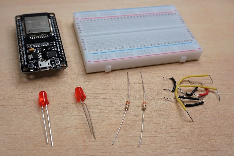
原文配件一览:ESP32 开发板、两颗 LED、两个 330Ω 电阻和面包板。
二、接线:GPIO 26 和 GPIO 27 各带一颗 LED
接线非常简单,两路完全对称:GPIO 26 接第一颗 LED 的正极(长脚),LED 负极串一个 330Ω 电阻回 GND;GPIO 27 同样接法带第二颗 LED。330Ω 是限流用的,别省,直接把 LED 正负极怼上 GPIO 会缩短引脚和 LED 的寿命。
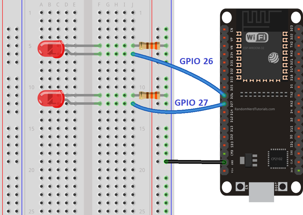
原文给出的接线原理图,GPIO 26 与 GPIO 27 两路对称。
这里有个新手常踩的点:ESP32 的 GPIO 编号和板子丝印不一定一一对应,接线前对照自己板子的引脚图确认 26 和 27 的物理位置,别按位置数错。这两颗 LED 原文初始状态都设为 LOW,也就是上电默认熄灭。
三、完整代码:STA 连路由器,80 端口起服务
先贴完整程序,后面拆开讲。把 ssid 和 password 换成你家路由器的名字和密码:
/*********
Rui Santos
Complete project details at http://randomnerdtutorials.com
*********/
// Load Wi-Fi library
#include "WiFi.h"
// Replace with your network credentials
const char* ssid = "REPLACE_WITH_YOUR_SSID";
const char* password = "REPLACE_WITH_YOUR_PASSWORD";
// Set web server port number to 80
WiFiServer server(80);
// Variable to store the HTTP request
String header;
// Auxiliar variables to store the current output state
String output26State = "off";
String output27State = "off";
// Assign output variables to GPIO pins
const int output26 = 26;
const int output27 = 27;
// Current time
unsigned long currentTime = millis();
// Previous time
unsigned long previousTime = 0;
// Define timeout time in milliseconds (example: 2000ms = 2s)
const long timeoutTime = 2000;
void setup() {
Serial.begin(115200);
// Initialize the output variables as outputs
pinMode(output26, OUTPUT);
pinMode(output27, OUTPUT);
// Set outputs to LOW
digitalWrite(output26, LOW);
digitalWrite(output27, LOW);
// Connect to Wi-Fi network with SSID and password
Serial.print("Connecting to ");
Serial.println(ssid);
WiFi.begin(ssid, password);
while (WiFi.status() != WL_CONNECTED) {
delay(500);
Serial.print(".");
}
// Print local IP address and start web server
Serial.println("");
Serial.println("WiFi connected.");
Serial.println("IP address: ");
Serial.println(WiFi.localIP());
server.begin();
}
void loop(){
WiFiClient client = server.available(); // Listen for incoming clients
if (client) { // If a new client connects,
currentTime = millis();
previousTime = currentTime;
Serial.println("New Client."); // print a message out in the serial port
String currentLine = ""; // make a String to hold incoming data from the client
while (client.connected() && currentTime - previousTime <= timeoutTime) { // loop while the client's connected
currentTime = millis();
if (client.available()) { // if there's bytes to read from the client,
char c = client.read(); // read a byte, then
Serial.write(c); // print it out the serial monitor
header += c;
if (c == '\n') { // if the byte is a newline character
// if the current line is blank, you got two newline characters in a row.
// that's the end of the client HTTP request, so send a response:
if (currentLine.length() == 0) {
// HTTP headers always start with a response code (e.g. HTTP/1.1 200 OK)
// and a content-type so the client knows what's coming, then a blank line:
client.println("HTTP/1.1 200 OK");
client.println("Content-type:text/html");
client.println("Connection: close");
client.println();
// turns the GPIOs on and off
if (header.indexOf("GET /26/on") >= 0) {
Serial.println("GPIO 26 on");
output26State = "on";
digitalWrite(output26, HIGH);
} else if (header.indexOf("GET /26/off") >= 0) {
Serial.println("GPIO 26 off");
output26State = "off";
digitalWrite(output26, LOW);
} else if (header.indexOf("GET /27/on") >= 0) {
Serial.println("GPIO 27 on");
output27State = "on";
digitalWrite(output27, HIGH);
} else if (header.indexOf("GET /27/off") >= 0) {
Serial.println("GPIO 27 off");
output27State = "off";
digitalWrite(output27, LOW);
}
// Display the HTML web page
client.println("");
client.println("");
client.println("");
// CSS to style the on/off buttons
// Feel free to change the background-color and font-size attributes to fit your preferences
client.println("");
// Web Page Heading
client.println("ESP32 Web Server");
// Display current state, and ON/OFF buttons for GPIO 26
client.println("GPIO 26 - State " + output26State + "
");
// If the output26State is off, it displays the ON button
if (output26State=="off") {
client.println("ON
");
} else {
client.println("OFF
");
}
// Display current state, and ON/OFF buttons for GPIO 27
client.println("GPIO 27 - State " + output27State + "
");
// If the output27State is off, it displays the ON button
if (output27State=="off") {
client.println("ON
");
} else {
client.println("OFF
");
}
client.println("");
// The HTTP response ends with another blank line
client.println();
// Break out of the while loop
break;
} else { // if you got a newline, then clear currentLine
currentLine = "";
}
} else if (c != '\r') { // if you got anything else but a carriage return character,
currentLine += c; // add it to the end of the currentLine
}
}
}
// Clear the header variable
header = "";
// Close the connection
client.stop();
Serial.println("Client disconnected.");
Serial.println("");
}
}
程序结构拆开看就三块。第一块是联网:WiFi.begin(ssid, password) 让 ESP32 以 STA 模式去连路由器(不是自己开热点的 AP 模式),连不上就在串口监视器里每 500ms 打一个点,连上后用 WiFi.localIP() 打印分配到的 IP,然后 server.begin() 在 80 端口把 HTTP 服务开起来。
第二块是 GPIO 初始化:pinMode 把 26、27 设成输出,digitalWrite 拉低,保证上电不误亮。
第三块是 loop() 里的主循环:server.available() 监听有没有客户端进来,有的话把 HTTP 请求头一个字符一个字符读进 header 字符串,读到空行说明请求头结束。这里原文页面上的代码有一行注释少打了一个斜杠,上面这份完整程序是从原作者的代码仓库直接取的,是对的,不用担心。
四、浏览器点按钮时发生了什么
这套服务器的"路由"逻辑特别直白:浏览器每点一次按钮,就是发一个 GET 请求,ESP32 在请求头里做字符串匹配:
// turns the GPIOs on and off
if (header.indexOf("GET /26/on") >= 0) {
Serial.println("GPIO 26 on");
output26State = "on";
digitalWrite(output26, HIGH);
} else if (header.indexOf("GET /26/off") >= 0) {
Serial.println("GPIO 26 off");
output26State = "off";
digitalWrite(output26, LOW);
} else if (header.indexOf("GET /27/on") >= 0) {
Serial.println("GPIO 27 on");
output27State = "on";
digitalWrite(output27, HIGH);
} else if (header.indexOf("GET /27/off") >= 0) {
Serial.println("GPIO 27 off");
output27State = "off";
digitalWrite(output27, LOW);
}
四个地址分别是 /26/on、/26/off、/27/on、/27/off,匹配到哪个就把对应 GPIO 拉高或拉低,同时更新状态变量。然后 ESP32 把一张写好的网页发回浏览器,网页上每个 GPIO 下面一个按钮:状态是 off 就显示绿色 ON 按钮(颜色值 #4CAF50),状态是 on 就显示灰色 OFF 按钮(#555555)。按钮本质上是个链接,点下去就是发起下一次 GET 请求,如此往复。
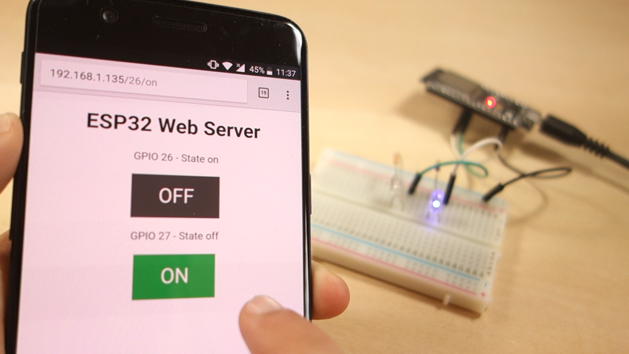
浏览器里看到的样子:两个 GPIO 的状态文字加 ON/OFF 按钮。
五、烧录、拿 IP、开控制
流程走一遍:代码里改好 ssid 和 password,选对板卡和串口,点上传。传完后打开串口监视器(115200),按一下板上 EN 复位键,等它连上路由器,监视器会打出类似这样的内容:
WiFi connected.
IP address:
192.168.1.135
192.168.1.135 是原文演示时的地址,你的会是路由器分配的另一个内网 IP。拿手机连到同一个 WiFi,浏览器地址栏直接输这个 IP,就能看到控制页面。点 ON,板上的 LED 立刻亮,页面按钮变成灰色 OFF;再点一下熄灭。注意手机和 ESP32 必须在同一局域网,这个方案是纯内网的,出了家门访问不到。
还有两个小坑提前说。一是手机浏览器有时会缓存旧页面,看到状态对不上就下拉刷新;二是原文代码里给每个客户端设了 2000ms 的超时(timeoutTime),浏览器打开太多标签连着它,可能出现响应变慢,属于正常现象,刷新即可。
结尾
这套 WiFiServer 写法的好处是零依赖、逻辑全暴露,读一遍就把 HTTP 请求-响应的来龙去脉看明白了,特别适合第一次接触网络编程的人。它的局限也明显:一次只能伺候一个客户端,网页是字符串拼出来的,状态靠整页刷新。等你在串口监视器里把请求头看得滚瓜烂熟,再往 WebServer 库、异步服务器那条路走,就会顺很多。先把 LED 点亮,后面的事好说。






照这个流程昨天终于把家里的 ESP32 点亮了,之前一直卡在串口监视器乱码,原来是波特率没设 115200。把请求头在监视器里打印出来这段特别有启发,第一次亲眼看到浏览器发的 GET 长什么样,比看书上讲 HTTP 直观多了。就是发现手机连了 5G 频段的 WiFi 就访问不到,换回 2.4G 的才行,不知道是不是我路由器的问题。
这个方案零依赖挺香的,就是在浏览器拼字符串发网页,哪天想加个温湿度显示再回来学 WebServer 库。
提醒一下各位,26 和 27 的物理位置别数错丝印,我第一次就接反了,查了半天代码结果纯接线问题。
GPIO 26/27 各带一颗 LED,330Ω 限流,然后 WiFiServer 80 端口收请求,用 header.indexOf 匹配 /26/on 这种地址来开关——比 MQTT 方案少一个 broker,纯内网玩具够用了。