
电池项目最怕什么?怕的是 ESP32 全速跑着 Wi-Fi,一晚上把 18650 干到没电。深睡眠(Deep Sleep)就是干这个的:CPU、大部分 RAM、数字外设全部断电,只留 RTC 控制器、RTC 外设和 RTC 内存活着,整机功耗直接掉一个量级。手上那批挂在户外靠太阳能小电池硬扛的节点,最后都是靠深睡眠续命的。这次把 ESP32 的四种唤醒源——定时器、触摸、外部分别用 ext0/ext1 实操一遍,代码全部逐字符核对过原例程,照抄就能跑。
先说清楚为什么非要折腾睡眠。Active 模式下射频一开,电流是百毫安级别的,一块 18650 两千多毫安时撑不了几天;深睡眠模式只养 RTC 域那一点点逻辑,电流直接降到微安级。Espressif 数据手册里给过各模式的功耗对照表,差距就是几十到几千倍的级别。你不需要精确记数字,只要记住一件事:电池项目不睡就是慢性自杀。
深睡眠到底关了什么
ESP32 有五种电源模式:Active、Modem Sleep、Light Sleep、Deep Sleep、Hibernation。深睡眠之后还可以更进一步进 Hibernation,但唤醒源也更受限。对多数电池项目,Deep Sleep 就是甜点位。
进深睡眠后,唯一还带电的是 RTC 域:RTC 控制器、RTC 外设、RTC 内存(约 8KB fast memory)。所以挂在 RTC 内存里的变量能跨睡眠存活,但按 EN 键硬件复位就会清掉。无线和主核全关,省电省的就是这一块。
这套模型对写惯了 Arduino 的人是反直觉的。你平常把逻辑写在 loop() 里让它反复转,深睡眠下这套思路整个作废——esp_deep_sleep_start() 之后再没有"醒来接着跑"这回事,芯片醒来等于一次软重启,setup() 从头执行。想跨睡眠记住状态,唯一的正规姿势就是 RTC_DATA_ATTR。
写法上有个固定套路,三步走:
- 第一步:配置唤醒源(定时器、触摸、外部 ext0/ext1,或者 ULP 协处理器);
- 第二步:按需决定外设上下电,默认 ESP32 会自动关掉唤醒源用不到的外设;
- 第三步:调 esp_deep_sleep_start() 进睡。它之后的代码永远不会执行,醒来后程序从头重跑 setup(),loop() 形同虚设。
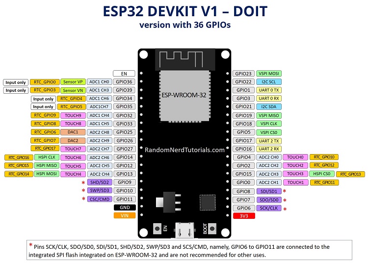
能用作外部唤醒的只有 RTC GPIO。经典 ESP32 上是这些脚:0、2、4、12-15、25-27、32-39,别的脚睡着时叫不醒它。
唤醒源一:定时器唤醒
定时器唤醒最简单,核心一句:
esp_sleep_enable_timer_wakeup(time_in_us)
参数单位是微秒,别按秒传。惯用做法是配两个宏做换算:uS_TO_S_FACTOR 设为 1000000ULL(微秒转秒的系数,注意 ULL 后缀防溢出),TIME_TO_SLEEP 设为 5(睡 5 秒),随后把 TIME_TO_SLEEP 乘以 uS_TO_S_FACTOR 传进去即可。
完整例程就在 Arduino IDE 的 文件-示例-ESP32-Deep Sleep-TimerWakeUp 里,原文代码如下:
/* Simple Deep Sleep with Timer Wake Up
   ESP32 offers a deep sleep mode for effective power saving as power is an important factor for IoT applications. In this mode CPUs, most of the RAM, and all the digital peripherals which are clocked
   from APB_CLK are powered off. The only parts of the chip which can still be powered on are: RTC controller, RTC peripherals ,and RTC memories This code displays the most basic deep sleep with a timer to wake it up and how to store data in RTC memory to use it over reboots This code is under Public Domain License.
   Author: Pranav Cherukupalli  */

#define uS_TO_S_FACTOR 1000000ULL  // Conversion factor for micro seconds to seconds
#define TIME_TO_SLEEP  5           // Time ESP32 will go to sleep (in seconds)

RTC_DATA_ATTR int bootCount = 0;

// Method to print the reason by which ESP32 has been awaken from sleep
void print_wakeup_reason(){
  esp_sleep_wakeup_cause_t wakeup_reason;

  wakeup_reason = esp_sleep_get_wakeup_cause();

  switch(wakeup_reason)
  {
    case ESP_SLEEP_WAKEUP_EXT0 : Serial.println("Wakeup caused by external signal using RTC_IO"); break;
    case ESP_SLEEP_WAKEUP_EXT1 : Serial.println("Wakeup caused by external signal using RTC_CNTL"); break;
    case ESP_SLEEP_WAKEUP_TIMER : Serial.println("Wakeup caused by timer"); break;
    case ESP_SLEEP_WAKEUP_TOUCHPAD : Serial.println("Wakeup caused by touchpad"); break;
    case ESP_SLEEP_WAKEUP_ULP : Serial.println("Wakeup caused by ULP program"); break;
    default : Serial.printf("Wakeup was not caused by deep sleep: %d\n",wakeup_reason); break;
  }
}

void setup(){
  Serial.begin(115200);
  delay(1000); // Take some time to open up the Serial Monitor

  // Increment boot number and print it every reboot
  ++bootCount;
  Serial.println("Boot number: " + String(bootCount));

  // Print the wakeup reason for ESP32
  print_wakeup_reason();

  // First we configure the wake up source We set our ESP32 to wake up every 5 seconds
  esp_sleep_enable_timer_wakeup(TIME_TO_SLEEP * uS_TO_S_FACTOR);
  Serial.println("Setup ESP32 to sleep for every " + String(TIME_TO_SLEEP) +
  " Seconds");

  /*
  Next we decide what all peripherals to shut down/keep on
  By default, ESP32 will automatically power down the peripherals
  not needed by the wakeup source, but if you want to be a poweruser
  this is for you. Read in detail at the API docs
  http://esp-idf.readthedocs.io/en/latest/api-reference/system/deep_sleep.html
  Left the line commented as an example of how to configure peripherals.
  The line below turns off all RTC peripherals in deep sleep.
  */
  //esp_deep_sleep_pd_config(ESP_PD_DOMAIN_RTC_PERIPH, ESP_PD_OPTION_OFF);
  //Serial.println("Configured all RTC Peripherals to be powered down in sleep");

  // Now that we have setup a wake cause and if needed setup the peripherals state in deep sleep, we can now start going to deep sleep.
  // In the case that no wake up sources were provided but deep sleep was started, it will sleep forever unless hardware reset occurs.
  Serial.println("Going to sleep now");
  delay(1000);
  Serial.flush();
  esp_deep_sleep_start();
  Serial.println("This will never be printed");
}

void loop(){
  // This is not going to be called
}
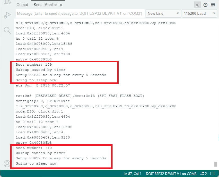
三个细节值得抠:RTC_DATA_ATTR int bootCount 把变量放进 RTC 内存,跨睡眠累加,每次醒来 boot number 加一;烧进去之后打开 115200 串口监视器,每 5 秒刷一次 boot number 和唤醒原因;按 EN 键硬件复位会把 RTC 内存清空,boot number 回到 1。睡觉前先 Serial.flush() 再睡,不然串口输出会被截断——这个坑不少人踩过。
定时唤醒的精度也值得一提:RTC 定时器的计时粒度比 millis() 细得多,传微秒级参数是认真的,不是摆设。想睡 37.5 秒,就写 37500000,不用取整凑整。不过长周期下别指望它当钟表用,它没有校准补偿,长时间累计会有漂移,对时间敏感的上报策略最好配合 NTP 校时做,纯靠 RTC 计时攒"每天"是攒不准的。
唤醒源二:触摸唤醒
触摸唤醒靠 touchSleepWakeUpEnable(触摸脚, 阈值) 一句配置。阈值方向要记牢:读值被摸时会往下掉,掉到阈值以下就醒。经典 ESP32 上阈值 40 越大越灵敏;ESP32-S2/S3 读值方向不同,默认阈值给 5000,越小越灵敏:
#if CONFIG_IDF_TARGET_ESP32
#define THRESHOLD 40   /* Greater the value, more the sensitivity */
#else                  //ESP32-S2 and ESP32-S3 + default for other chips (to be adjusted) */
#define THRESHOLD 5000 /* Lower the value, more the sensitivity */
#endif
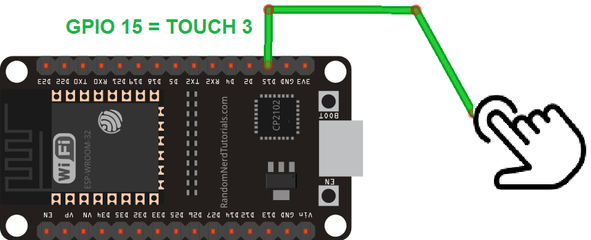
触摸脚和 GPIO 的对应关系(经典 ESP32):T0=GPIO4、T1=GPIO0、T2=GPIO2、T3=GPIO15、T4=GPIO13、T5=GPIO12、T6=GPIO14、T7=GPIO27、T8=GPIO33、T9=GPIO32。接线极简:往 GPIO15(T3)上焊一根杜邦线当触摸电极就行。原例程在 T3 + T7(GPIO15 + GPIO27)两个脚上同时使能了唤醒:
RTC_DATA_ATTR int bootCount = 0;
touch_pad_t touchPin;

void print_wakeup_touchpad() {
  touchPin = (touch_pad_t) esp_sleep_get_touchpad_wakeup_status();

#if CONFIG_IDF_TARGET_ESP32
  switch (touchPin) {
    case 0:  Serial.println("Touch detected on GPIO 4"); break;
    case 1:  Serial.println("Touch detected on GPIO 0"); break;
    case 2:  Serial.println("Touch detected on GPIO 2"); break;
    case 3:  Serial.println("Touch detected on GPIO 15"); break;
    case 4:  Serial.println("Touch detected on GPIO 13"); break;
    case 5:  Serial.println("Touch detected on GPIO 12"); break;
    case 6:  Serial.println("Touch detected on GPIO 14"); break;
    case 7:  Serial.println("Touch detected on GPIO 27"); break;
    case 8:  Serial.println("Touch detected on GPIO 33"); break;
    case 9:  Serial.println("Touch detected on GPIO 32"); break;
    default: Serial.println("Wakeup not by touchpad"); break;
  }
#else
  if (touchPin < TOUCH_PAD_MAX) {
    Serial.printf("Touch detected on GPIO %d\n", touchPin);
  } else {
    Serial.println("Wakeup not by touchpad");
  }
#endif
}
setup() 里只多这两句,然后就 esp_deep_sleep_start():
#if CONFIG_IDF_TARGET_ESP32
  //Setup sleep wakeup on Touch Pad 3 + 7 (GPIO15 + GPIO 27)
  touchSleepWakeUpEnable(T3, THRESHOLD);
  touchSleepWakeUpEnable(T7, THRESHOLD);

#else  //ESP32-S2 + ESP32-S3
  //Setup sleep wakeup on Touch Pad 3 (GPIO3)
  touchSleepWakeUpEnable(T3, THRESHOLD);

#endif
跑起来后摸那根线,串口会打出 boot number、唤醒原因 Touchpad、以及具体是哪个 GPIO 被摸了。注意芯片差异:经典 ESP32 可以多触摸脚同时当唤醒源,S2/S3 只支持一个。
这套玩法在极客手里能玩出花:一根焊在触摸脚上的裸线就是传感器,不需要任何物理按键,外壳做全密封照样能交互。户外的动物观察盒、藏在花盆里的土壤提醒器,都可以"隔空一碰就开机"。不过有个工程细节要留意:阈值 40 是在理想环境下调的,如果你的电极线很长或者贴着金属外壳,读值基线会漂,最好实际摸一下打印读值再定阈值,照抄默认值不一定一次就灵敏。
唤醒源三:外部唤醒 ext0 与 ext1
外部唤醒分两档。ext0:单个 GPIO,走 RTC_IO 唤醒,要求 RTC 外设保持供电,配置一句 esp_sleep_enable_ext0_wakeup(GPIO_NUM_X, level),level 填 1 高电平醒、0 低电平醒。ext1:多个 GPIO,走 RTC 控制器,RTC 外设可以断电更省电,配置 esp_sleep_enable_ext1_wakeup_io(位掩码, mode);经典 ESP32 的 mode 只有 ALL_LOW 和 ANY_HIGH 两种,S2/S3/C6/H2 上另有 ANY_LOW。
位掩码有个现成宏:
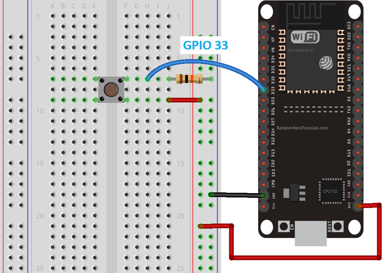
#define BUTTON_PIN_BITMASK(GPIO) (1ULL << GPIO) // 2 ^ GPIO_NUMBER in hex原例程用 GPIO33 接按键、10K 电阻下拉到地,ext0 方式唤醒:
#include "driver/rtc_io.h"

#define BUTTON_PIN_BITMASK(GPIO) (1ULL << GPIO)  // 2 ^ GPIO_NUMBER in hex
#define USE_EXT0_WAKEUP          1               // 1 = EXT0 wakeup, 0 = EXT1 wakeup
#define WAKEUP_GPIO              GPIO_NUM_33     // Only RTC IO are allowed - ESP32 Pin example
RTC_DATA_ATTR int bootCount = 0;

void print_wakeup_reason() {
  esp_sleep_wakeup_cause_t wakeup_reason;

  wakeup_reason = esp_sleep_get_wakeup_cause();

  switch (wakeup_reason) {
    case ESP_SLEEP_WAKEUP_EXT0:     Serial.println("Wakeup caused by external signal using RTC_IO"); break;
    case ESP_SLEEP_WAKEUP_EXT1:     Serial.println("Wakeup caused by external signal using RTC_CNTL"); break;
    case ESP_SLEEP_WAKEUP_TIMER:    Serial.println("Wakeup caused by timer"); break;
    case ESP_SLEEP_WAKEUP_TOUCHPAD: Serial.println("Wakeup caused by touchpad"); break;
    case ESP_SLEEP_WAKEUP_ULP:      Serial.println("Wakeup caused by ULP program"); break;
    default:                        Serial.printf("Wakeup was not caused by deep sleep: %d\n", wakeup_reason); break;
  }
}

void setup() {
  Serial.begin(115200);
  delay(1000);  //Take some time to open up the Serial Monitor

  //Increment boot number and print it every reboot
  ++bootCount;
  Serial.println("Boot number: " + String(bootCount));

  //Print the wakeup reason for ESP32
  print_wakeup_reason();

  /*
    First we configure the wake up source
    We set our ESP32 to wake up for an external trigger.
    There are two types for ESP32, ext0 and ext1 .
    ext0 uses RTC_IO to wakeup thus requires RTC peripherals
    to be on while ext1 uses RTC Controller so does not need
    peripherals to be powered on.
    Note that using internal pullups/pulldowns also requires
    RTC peripherals to be turned on.
  */
#if USE_EXT0_WAKEUP
  esp_sleep_enable_ext0_wakeup(WAKEUP_GPIO, 1);  //1 = High, 0 = Low
  // Configure pullup/downs via RTCIO to tie wakeup pins to inactive level during deepsleep.
  // EXT0 resides in the same power domain (RTC_PERIPH) as the RTC IO pullup/downs.
  // No need to keep that power domain explicitly, unlike EXT1.
  rtc_gpio_pullup_dis(WAKEUP_GPIO);
  rtc_gpio_pulldown_en(WAKEUP_GPIO);

#else  // EXT1 WAKEUP
  //If you were to use ext1, you would use it like
  esp_sleep_enable_ext1_wakeup_io(BUTTON_PIN_BITMASK(WAKEUP_GPIO), ESP_EXT1_WAKEUP_ANY_HIGH);
  /*
    If there are no external pull-up/downs, tie wakeup pins to inactive level with internal pull-up/downs via RTC IO
         during deepsleep. However, RTC IO relies on the RTC_PERIPH power domain. Keeping this power domain on will
         increase some power comsumption. However, if we turn off the RTC_PERIPH domain or if certain chips lack the RTC_PERIPH
         domain, we will use the HOLD feature to maintain the pull-up and pull-down on the pins during sleep.
  */
  rtc_gpio_pulldown_en(WAKEUP_GPIO);  // GPIO33 is tie to GND in order to wake up in HIGH
  rtc_gpio_pullup_dis(WAKEUP_GPIO);   // Disable PULL_UP in order to allow it to wakeup on HIGH
#endif
  //Go to sleep now
  Serial.println("Going to sleep now");
  esp_deep_sleep_start();
  Serial.println("This will never be printed");
}

void loop() {
  //This is not going to be called
}这里的上下拉配置是关键:rtc_gpio_pulldown_en() 把脚拉住低电平,rtc_gpio_pullup_dis() 关掉上拉防止脚被意外拉高,这样按键没按是稳定 LOW、按下变 HIGH 才醒,不会随机乱醒。
ext0 和 ext1 怎么选?我的经验是:单按键、要最省事的场景直接 ext0;要两个以上触发源(比如门磁加急停按钮)、或者睡眠期间想连 RTC 外设一起断电抠功耗的场景,必须走 ext1。ext1 还有个隐性优势:它允许 RTC_PERIPH 电源域整体关闭,深睡眠电流能再往下压一截,代价是内部上下拉要靠 HOLD 特性维持,注释里写得很清楚。
ext1 多脚唤醒的写法,两个 GPIO 的掩码用或运算拼起来:
#define WAKEUP_GPIO_2              GPIO_NUM_2     // Only RTC IO are allowed - ESP32 Pin example
#define WAKEUP_GPIO_15              GPIO_NUM_15     // Only RTC IO are allowed - ESP32 Pin example

// Define bitmask for multiple GPIOs
uint64_t bitmask = BUTTON_PIN_BITMASK(WAKEUP_GPIO_2) | BUTTON_PIN_BITMASK(WAKEUP_GPIO_15);
想知道具体是哪个 GPIO 醒的,用 esp_sleep_get_ext1_wakeup_status() 拿回掩码再取对数:
void print_GPIO_wake_up(){
  int GPIO_reason = esp_sleep_get_ext1_wakeup_status();
  Serial.print("GPIO that triggered the wake up: GPIO ");
  Serial.println((log(GPIO_reason))/log(2), 0);
}
第四种:ULP 协处理器
严格说还有一路 ULP 协处理器唤醒——它能在深睡眠里跑存在 RTC 内存里的小程序,定时去读外设、RTC 定时器和内部传感器,读到位了再叫醒主核。低功耗采样场景很有想象力,本篇不展开,官方文档里另有专章。它也是四种唤醒源里门槛最高的一路,汇编写法在文档里都是官方未公布完整教程的那种只给骨架,得自己啃 IDF 手册。
引脚速查与踩坑点
| 唤醒方式 | 关键 API | 可用脚 |
|---|---|---|
| 定时器 | esp_sleep_enable_timer_wakeup(微秒) | 不占脚 |
| 触摸 | touchSleepWakeUpEnable(脚, 阈值) | T0-T9 对应 GPIO4/0/2/15/13/12/14/27/33/32 |
| 外部 ext0 | esp_sleep_enable_ext0_wakeup(脚, 电平) | RTC GPIO:0、2、4、12-15、25-27、32-39 |
| 外部 ext1 | esp_sleep_enable_ext1_wakeup_io(掩码, mode) | 同上,可多脚 |
最后几条实战提醒:第一,rtc_io.h 这个头文件在原文里是 #include "driver/rtc_io.h" 带引号写法,平台转义后一律用双引号,编译等价;第二,唤醒后程序从 setup() 开头重跑,任何"只跑一次"的逻辑都得自己拿 RTC_DATA_ATTR 变量区分冷启动和睡眠唤醒;第三,没有配唤醒源就直接 esp_deep_sleep_start(),会睡死过去,只能按 EN 硬复位救回来。把定时器当心跳、触摸和 ext 当交互,这三件套组合起来,电池供电的传感器节点就能按分钟级甚至小时级的节奏醒来干活,寿命完全够一个季节不用换电池。
再补充两个容易翻车的组合技。一是定时唤醒加 Wi-Fi 的项目,醒来联网上报那几十秒才是耗电大头,睡眠周期设计得再漂亮也架不住每次醒来都重连路由器重试,弱网环境下记得给联网流程设个超时放弃。二是多个唤醒源可以叠加配置,比如定时器兜底加按键触发,esp_sleep_enable_timer_wakeup 和 esp_sleep_enable_ext0_wakeup 各配各的、互不冲突,醒后用 esp_sleep_get_wakeup_cause() 判断这次是谁叫的,再走不同的处理分支,这是低功耗节点最实用的骨架结构。


这篇把我上个月踩的坑全讲到了:Serial.flush() 之前没加,串口打印永远缺半截,排查了一晚上才发现是没等输出发完就睡了。补一句经验,如果你睡眠周期短于串口打开时间,monitor 里前几行 boot log 也会被吞,delay(1000) 那句真不是摆设。
ext1 的 bitmask 用 1ULL
触摸唤醒那根线玩法有点意思,全密封外壳也能做交互。
问一下各位,定时唤醒加 NTP 校时这套有没有现成例程?我这 RTC 累计漂移一天能差出几十秒,文章里说的这点深有体会。